Transmission Input Speed Sensor Location: Where to Find It
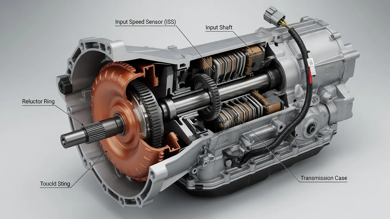
The transmission input speed sensor is usually mounted on the transmission case near the front, close to the bellhousing, where it can read the rotation of the input or turbine shaft. That general rule has real exceptions. Depending on the transmission type, the sensor may sit on the side or top of the case, hide under other components, or live inside the unit on the valve body. Below is where to look, why the placement varies, and how to confirm the location for your specific vehicle.
Where the input speed sensor is usually located
On most conventional automatic transmissions and transaxles with an external sensor, you will find it on the outside of the case toward the engine end. It is typically a small cylindrical sensor held in a bore by a single bolt, sealed with an O-ring, and fitted with a two- or three-wire electrical connector. Service information may call it the input speed sensor (ISS), turbine speed sensor (TSS) or input shaft speed sensor. These names usually describe the same job: measuring how fast the transmission input is turning.
On front-wheel-drive transaxles, the sensor is often on the top or front face of the case near the bellhousing. It may be buried under the battery tray, air intake ducting or wiring brackets, so access from above sometimes requires removing those parts first. On rear-wheel-drive and many four-wheel-drive vehicles, it is commonly on the side of the case near the bellhousing and is reached from underneath. Many transmissions also carry an output speed sensor, usually toward the rear of the case or tail housing on rear-wheel-drive units, or near the final drive on transaxles. The two can look identical, so confirm which one you are looking at before unplugging or replacing anything.
How the input speed sensor works
The sensor faces a toothed tone ring on the input shaft, the turbine shaft, or a clutch drum driven by the torque converter turbine. As the teeth pass the sensor tip, it produces a pulsing signal whose frequency rises with shaft speed. Two designs are common. A magnetic pickup, usually two wires, generates its own alternating signal. A Hall-effect sensor, usually three wires for power, ground and signal, produces a square-wave signal. Because the sensor has to read a component driven by the converter, it ends up near the front of the transmission, which explains the typical location.
The transmission control module compares input speed with output speed to calculate the gear ratio actually achieved, and with engine speed to calculate torque converter slip. It uses that information to time shifts, control pressure during a shift and manage converter lockup. When the signal drops out or does not make sense, the module may set diagnostic codes such as P0715, P0716 or P0717, or a manufacturer-specific code, and may switch to a failsafe mode with fixed gears. A code tells you the signal or circuit is out of expectation. It does not prove the sensor itself has failed, because wiring, connectors, debris on a magnetic tip, low fluid, internal mechanical faults and module problems can produce the same result.
What changes the location from one vehicle to another
The transmission type matters most. Some automatics place the input and output speed sensors inside the case, mounted on the valve body or built into an internal control module, so there is nothing to find on the outside. Continuously variable transmissions use a primary pulley speed sensor on the input side, often called the input or primary speed sensor. Dual-clutch transmissions usually monitor each input shaft separately, often with sensors inside the mechatronic unit. Manual transmissions generally do not use an input speed sensor for shift control, although some vehicles fit one for other functions. Some older electronically controlled automatics have no dedicated input speed sensor at all and rely on engine speed instead.
Even within one vehicle model, the answer can change with engine choice, two-wheel versus four-wheel drive, model year, or a mid-year transmission update. A diagram for the right model but the wrong transmission can send you to the wrong spot or to a sensor that does not exist on your unit. Treat any generic location as a starting point, not a confirmation.
How to find and check it on your vehicle
Start by identifying the exact transmission. The VIN, the transmission identification tag or stamping on the case, the build label, and past service history records can all narrow it down. A parts lookup by VIN will show whether the transmission uses an external input speed sensor and what it looks like. Factory service information or a reputable repair database will give the location diagram, access steps and torque specification for your configuration.
Once you know what to look for, follow the transmission wiring harness toward the front of the case and compare what you find with the diagram, keeping the output sensor in mind. Inspect the connector for poor seating, corrosion or bent terminals, the wiring for chafing or heat damage, and the sensor area for fluid seeping past the O-ring. With a scan tool, read stored codes and freeze-frame data, then watch live data for input or turbine speed alongside engine speed and output speed. A reading that stays at zero or drops out while the vehicle is moving in gear points to a signal problem worth tracing through the circuit. Also check fluid level and condition using the correct fluid specification and the manufacturer's checking procedure, since low or degraded fluid can affect both readings and shift behavior.
If testing points to the sensor, confirm fitment by part number before buying. An external sensor is often a simple swap: unplug it, remove the retaining bolt, ease it out, clean the bore, fit a new O-ring lightly lubricated with the specified fluid, install it and tighten to specification. Expect a little fluid loss on some units and top up correctly. An internal sensor typically means draining fluid and removing the pan or valve body, then refilling to the correct level with the specified fluid. Some vehicles also need module programming or a shift adaptation relearn. Afterward, clear codes, road test, and watch for normal shift behavior and a stable speed reading.
Limitations and when to get professional help
No single description covers every vehicle, so the exact location for yours depends on confirming the transmission first. Symptoms often blamed on this sensor, including harsh or delayed shifts, flaring between gears and limp mode, are shared with low fluid, solenoid faults, valve body wear, slipping clutches and software issues. Replacing the sensor without testing the signal can cost money without fixing the problem.
Consider a transmission specialist when the sensor is internal, when codes return after a repair, when you see slipping, burnt-smelling fluid or metal debris, or when programming or relearn procedures require dealer-level tools. Repair options range from a new sensor or a harness repair to fluid service or internal work, and the right choice comes from testing rather than the symptom alone. Always support the vehicle securely on stands and let a hot transmission cool before working near it.