What Is a Transmission Input Speed Sensor?
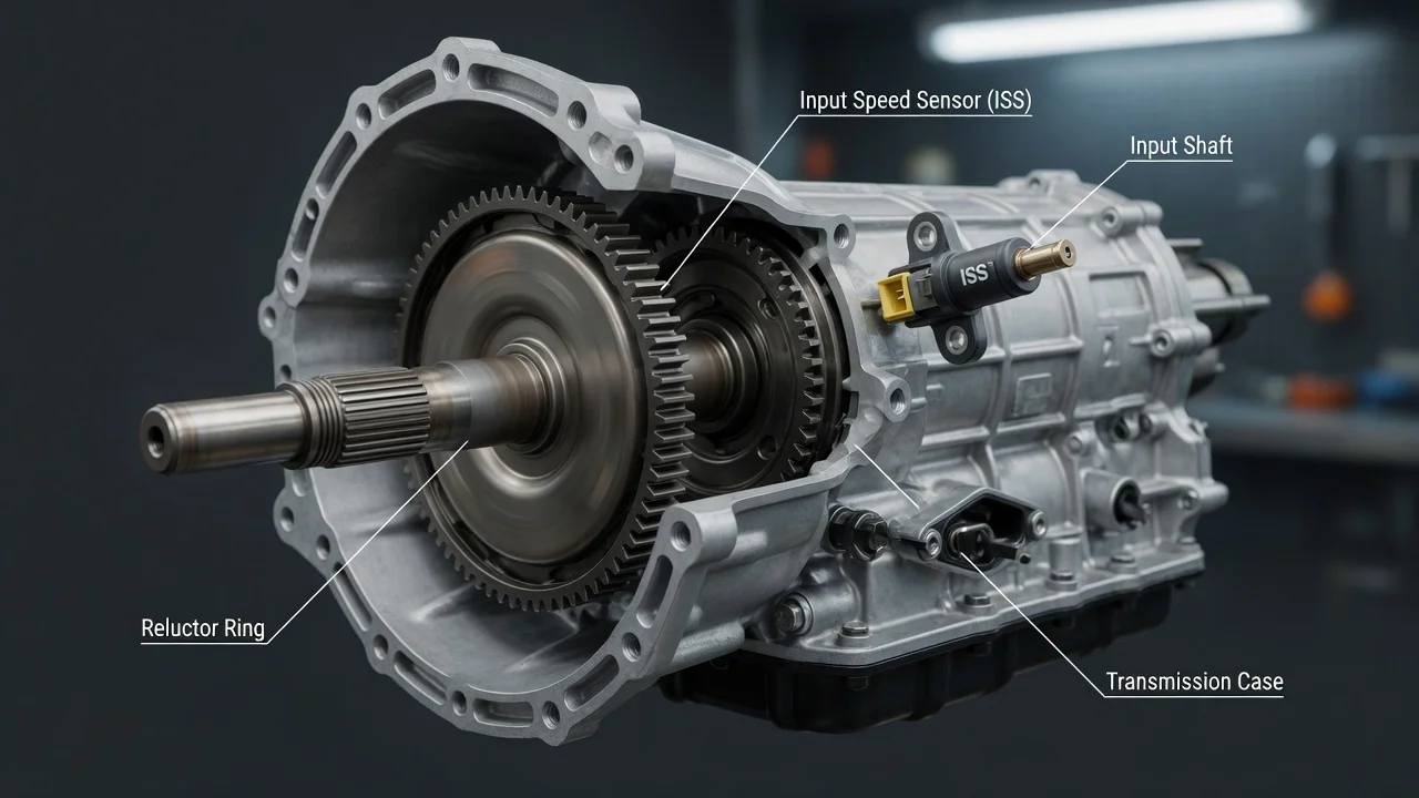
An input transmission speed sensor tells the transmission control module how fast the input side of the transmission is turning. It is a small part, but the computer relies on its signal for nearly every shift decision. This guide explains what the sensor does and how it works. It also covers how it differs between transmission types and what you can check yourself before choosing a repair.
What a transmission input speed sensor is
The transmission input speed sensor is often abbreviated ISS. In many automatic transmissions it is called the turbine speed sensor. It measures how fast the input shaft turns, or a part that turns with it, such as the torque converter turbine shaft or an input clutch drum. It sends that speed as an electrical signal to the transmission control module (TCM) or to a combined powertrain control module. The sensor controls nothing itself; it only measures. Its counterpart, the output speed sensor, measures how fast the output shaft turns. Not every vehicle has both, and manufacturers use different names. So when a parts listing or code description mentions an input sensor, match it to your specific transmission before drawing conclusions.
How the sensor works
Most input speed sensors read a ring with teeth or slots, called a tone ring or reluctor, on a rotating part. As each tooth passes the sensor tip, the signal changes. The module counts the pulses arriving per unit of time and calculates speed from them. There are two common designs. A magnetic pickup, also called a variable reluctance sensor, usually has two wires and generates its own alternating voltage. Both the frequency and the strength of that signal rise with speed. A Hall-effect or magnetoresistive sensor usually has three wires. It gets a supply voltage and ground from the module and switches its signal on and off, producing a square wave. The two designs are tested differently, which is one reason a generic test procedure can mislead.
The module uses the reading in several ways. Comparing input speed with output speed gives the gear ratio actually achieved, which shows whether a shift completed and how quickly. Comparing input speed with engine speed shows torque converter slip and whether the converter clutch is applied. Many transmissions also use this data to adjust clutch timing and pressure over time, so the shift behavior you feel depends partly on a good signal. If the signal is missing or implausible, many modules switch to a failsafe mode. They may hold a single gear, raise line pressure or stop applying the converter clutch.
What changes the answer
Transmission type is the first variable. In a conventional automatic, the input sensor typically reads the turbine shaft or an input drum. In a continuously variable transmission, the equivalent is usually a primary or drive pulley speed sensor. Dual-clutch transmissions commonly monitor each input shaft separately, so they may have more than one input speed sensor. Many manual transmissions have none. Some use one for functions such as rev matching or shift indication, so on a manual, check any code or part name against that specific gearbox.
Where the sensor sits matters just as much for repair. Some sensors mount on the outside of the case, held by a single bolt and sealed with an O-ring, and can be reached from underneath. Others are inside the transmission: under the pan, on the valve body, or built into a mechatronic unit or control module. An internal sensor may mean draining fluid and removing major components. A built-in one may mean replacing a whole assembly that then needs programming. Model year, engine and drivetrain can change the design even within one vehicle model. Confirm fitment by VIN or transmission identification, not by appearance.
Symptoms and codes are clues, not a verdict
A faulty input speed signal can cause harsh or erratic shifts, flared or delayed upshifts, or a transmission stuck in one gear. It can also stop the converter clutch from applying or turn on a warning light. Generic OBD-II diagnostic codes in the P0715 group cover the input or turbine speed sensor circuit. P0715 points to the circuit, P0716 to a range or performance problem, and P0717 to no signal. Manufacturers also use their own codes, and gear ratio or slip codes may appear alongside them.
None of these codes proves that the sensor itself has failed. A circuit code can come from a damaged harness, a corroded or loose connector, or a module fault. A no-signal code can follow a broken tone ring or metal debris on a magnetic sensor tip. A range or performance code can mean the sensor is reporting accurately on a transmission that really is slipping. The cause could be low fluid, worn clutches or a hydraulic fault. Replacing the sensor in that situation leaves the actual problem in place. The same shift symptoms can also occur with no sensor fault at all.
What the owner can check
Start with checks that need no special tools. Note exactly when the problem appears: cold or hot, at a particular gear change, after a stop, or only under load. Check the fluid level and condition using the method in your owner's manual or service information. Many transmissions have no dipstick and need the check done at a specific fluid temperature. Make sure any fluid added in the past matches the required fluid specification, because the wrong fluid can cause shift problems of its own. Review the service history for recent fluid service, repairs or wiring work near the transmission.
A scan tool that reads the transmission module is more useful than a basic code reader. Write down all stored codes and freeze-frame data before clearing anything. If the tool shows live data, compare input or turbine speed with engine speed and output speed while driving safely or with a helper. A reading that drops to zero, spikes, or fails to follow the other values points toward the signal path. A steady signal while the transmission slips points away from the sensor. If the sensor is mounted outside the case, inspect the connector for corrosion, bent pins or oil. Check the harness for chafing, and remove the sensor to look for debris or damage on the tip. Measure resistance or voltage only against the values in the service information for that exact part.
Replacing the sensor
If testing shows the sensor should be replaced, buy it by VIN or transmission code, because input and output sensors can look alike yet differ. Fit a new O-ring if the design uses one, tighten the bolt to the specified torque, clear the codes and road test. Some vehicles also need an adaptive relearn or reset before shifts feel normal again.
Limitations and when to get professional help
The right diagnostic path depends on the exact transmission, its sensor design and the module software. Generic advice cannot replace the test procedure for your vehicle. Telling a sensor fault apart from wiring, module or internal wear problems often takes wiring diagrams, an oscilloscope or manufacturer software. If the sensor is internal, part of a mechatronic unit, or needs programming, a professional repair is usually the practical choice.
Stop driving and get help promptly if the transmission slips, will not engage, overheats, smells burnt, or goes into limp mode at highway speed. Bring your codes, live data notes and service history to a transmission specialist. They can confirm the cause and recommend a repair, from fixing a connector to replacing the sensor or repairing internal parts, before more damage occurs.