Bad Transmission Input Speed Sensor Symptoms
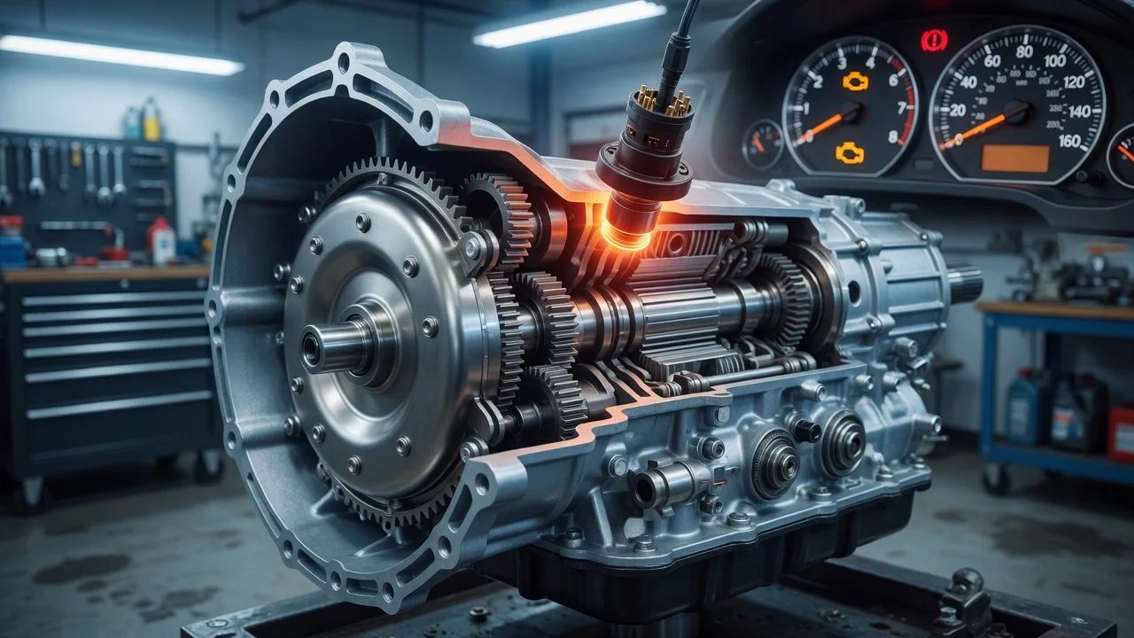
A failing transmission input speed sensor can make an automatic transmission shift harshly, hesitate or drop into a fail-safe mode. Wiring faults, low fluid and real internal wear can cause the same signs. This guide explains how to record what the vehicle is doing, separate the competing causes, run checks in a sensible order and decide what to do next. It does not assume the sensor is at fault until the evidence supports that conclusion.
What the input speed sensor does
The input speed sensor, called a turbine speed sensor on some vehicles, reports how fast the transmission input shaft or a related component is turning. The transmission control module compares that reading with engine speed and the output speed sensor signal. From these, it calculates the current gear ratio, torque converter slip and the timing of clutch application. If the input signal is missing, erratic or implausible, the module can no longer judge shifts accurately and often switches to a protective strategy.
Configuration matters. Conventional automatics, CVTs and dual-clutch units use speed sensing differently, and manufacturers name their sensors differently. Some sensors bolt into the outside of the case. Others sit inside the transmission, on the valve body or within an integrated control unit, so replacing them may require draining fluid or removing the pan. Sensors also differ electrically. Magnetic pickup types generate their own AC signal, while Hall-effect types need a supply voltage from the module. Before diagnosing anything, confirm the exact transmission type from the VIN, the build data or the identification label on the unit.
Establish the symptoms
Typical shift behavior linked to a bad or intermittent input speed signal includes: • Harsh or abrupt shifts. • Delayed engagement into drive or reverse. • Erratic or hunting upshifts and downshifts. • Flare, where engine revs rise briefly between gears. • The transmission holding a single gear in limp or fail-safe mode. A check engine or transmission warning light often appears. Some vehicles also stop engaging the torque converter clutch, which can raise cruising rpm, or disable cruise control. On many vehicles the speedometer relies on output or wheel speed signals, so a working speedometer does not clear the input sensor.
Record the conditions each time the problem appears: • Cold or fully warm transmission. • A particular speed or gear. • Over bumps or rough pavement, or after rain or a car wash. • Whether the symptom clears after the engine is switched off and restarted. Fail-safe strategies often reset on a new key cycle. Also note recent changes: a fluid service, transmission removal, wiring work or a battery disconnection. Gather the service history, including which fluid was used. A clear symptom log saves diagnostic time and helps a technician reproduce an intermittent fault.
Distinguish plausible causes
The sensor itself can fail through an open coil or failed internal electronics, and some fail only when hot. A circuit or no-signal code with intact wiring supports this cause, as does an input speed reading that drops out while output speed stays steady. A consistent, plausible input signal in live data weakens it. Wiring and connector faults are equally common: a harness chafed against the case or exhaust, corroded or loose pins, or fluid wicking into the connector. Symptoms that appear over bumps, codes that come and go, or several sensor codes on a shared circuit point toward wiring rather than the sensor.
Magnetic sensors attract metal fines. Enough debris on the tip can distort the signal, and heavy debris suggests internal wear elsewhere. A damaged tone ring or an incorrect air gap can also corrupt the reading. Other causes produce similar shift complaints with a healthy sensor: • Low or incorrect fluid. • Genuine clutch slip. • Solenoid or valve body faults. • A module or software problem. Range, performance or gear ratio codes can mean the sensor is accurately reporting a transmission that is actually slipping. Low, burnt or contaminated fluid supports an internal cause. Clean fluid at the correct level combined with a clear circuit fault weakens it.
Checks in a useful order
Owners can safely start with these checks: • Note any warning lights. • Read diagnostic codes with a scan tool and save the freeze frame data before clearing anything. Codes such as P0715 through P0718 relate to the input or turbine speed sensor circuit, but a basic reader may miss manufacturer-specific transmission codes. • With the engine off and cool, look for fluid leaks and visibly damaged or disconnected wiring near the transmission. • Check fluid level only if the vehicle has a dipstick, and follow the owner's manual procedure, which usually specifies temperature and gear position. Many sealed transmissions require a temperature-controlled check at a shop. Use only the fluid specification listed for that transmission.
The next steps need equipment, specifications or a qualified technician: • Compare input speed with engine rpm and output speed in live data during a road test. A technician can also wiggle the harness while watching for dropouts. • Test the sensor electrically against the service information: resistance and AC output for magnetic sensors, supply, ground and signal for Hall-effect sensors. An oscilloscope is ideal for either type. • Remove an external sensor to inspect the tip for debris, and check the tone ring where accessible. Sensors inside the transmission, pan removal, refilling sealed units and module programming are best left to a transmission shop.
Interpret the findings
Read the results as a set rather than one at a time: • A no-signal or circuit code, plus a sensor that fails its specified test while the wiring checks good, points strongly to the sensor. • A good signal at the sensor that does not reach the module points to wiring or the connector. • A plausible input signal alongside a range or gear ratio code shifts attention to fluid condition, actual slip, solenoids or the valve body. • Heavy metal on the sensor tip means cleaning may restore the signal, but the source of the debris still needs investigation. A symptom alone, or a code alone, does not confirm a failed part.
Before buying a part, confirm fitment by VIN. Input and output sensors often look alike, and connectors and lengths vary between transmission versions. After any repair, clear the codes and road test under the conditions that triggered the fault. Confirm that the live data input speed tracks engine and output speed sensibly and that no code returns. Some transmissions need an adaptive relearn after sensor or wiring repairs. An intermittent fault may require a longer test period before the repair can be considered verified.
Urgency and next action
Stop driving and arrange inspection or towing if any of these occur: • The vehicle will not engage drive or reverse. • Engine revs flare or climb without matching acceleration. • You notice a burning smell, an overheating warning or fluid leaking onto the ground. • You hear new grinding or clunking noises. • A gear stuck in fail-safe mode makes it hard to keep up with traffic. Fail-safe mode is intended to let you reach a safe place, not to support normal use. Continued driving with real slip can enlarge the repair. No reliable estimate of safe remaining distance can be given for a vehicle showing these signs.
Give the repair shop the following: • The VIN and transmission type. • All stored codes with their freeze frame data. • Your symptom log. • The service history, including the fluid used and any recent work. Repair options range from a connector or wiring repair, sensor replacement or a fluid correction to a software update or internal valve body or transmission repair. The right repair depends on the confirmed cause, not on the first symptom noticed.