Transmission Output Speed Sensor Location
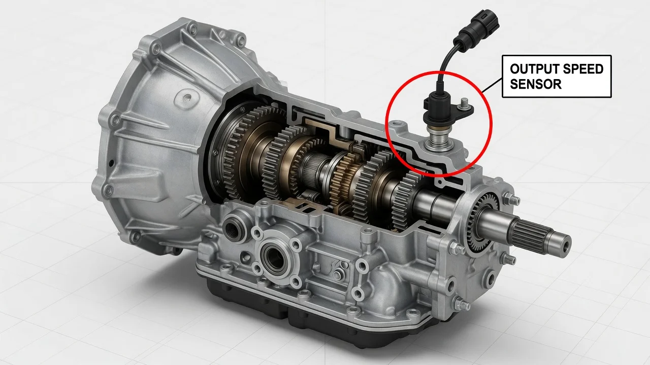
The transmission output speed sensor tells the vehicle's computer how fast the transmission's output shaft is turning. Knowing where it sits helps when you are chasing a speed-related trouble code, checking a wiring problem or planning a replacement. On most vehicles it is mounted on the outside of the transmission case near the output end. The exact spot depends on the transmission type and drivetrain layout.
Where the output speed sensor is usually found
On most automatic transmissions, the output speed sensor bolts into the transmission case close to where power leaves the unit. On a rear-wheel-drive vehicle, that usually means the rear portion of the case or the extension housing, just ahead of where the driveshaft connects. It is often on the side of the housing and held by a single bolt. A two- or three-wire electrical connector plugs into it, and an O-ring seals it against the case.
On front-wheel-drive transaxles, the sensor is usually on the transaxle case near the final drive or differential area, where the axle shafts exit. It may face forward, rearward or downward. It can also be partly hidden behind brackets, wiring harnesses or the air intake, so access from underneath is often the most practical. Some transmissions do not have an externally mounted output sensor at all, which is covered below.
How the sensor reads output shaft speed
The sensor watches a toothed ring, gear or reluctor attached to the output shaft or to a part that turns with it, such as the parking gear. As the teeth pass the sensor tip, it produces a pulsing signal. Older and simpler designs are often magnetic pickups that generate their own alternating voltage, usually with two wires. Many newer designs are Hall-effect or magnetoresistive sensors. These receive a reference voltage and ground from the control module and switch a signal, often using three wires.
The transmission control module, or the engine computer on some vehicles, compares output speed with input or turbine speed. From that comparison it works out which gear is engaged, whether clutches are slipping and when to command the next shift. The same information may feed the speedometer, cruise control and torque converter clutch logic. That is why a faulty signal can affect shift behavior, speedometer readings and other systems at the same time.
What changes the location on your vehicle
Transmission type matters most. Conventional automatics, dual-clutch units, CVTs and manual transmissions all measure output speed differently. Some manuals use a vehicle speed sensor on the case instead of a dedicated transmission output sensor. Drivetrain layout also changes the answer. On four-wheel-drive and all-wheel-drive vehicles, the sensor used for vehicle speed may be on the transfer case or power transfer unit rather than the transmission itself, and some vehicles have sensors in both places.
Several modern transmissions mount their speed sensors internally, either on the valve body or as part of an integrated control unit inside the case. On those designs, reaching the sensor may require draining fluid and removing the pan or a cover. The sensor may also only be serviced as part of a larger assembly. Other vehicles calculate road speed from the ABS wheel speed sensors and use them alongside, or instead of, a transmission output signal. Location can differ by engine, model year or drivetrain even within one model, so confirm fitment by VIN rather than by model name alone.
How to find and check it yourself
Start by identifying the exact transmission. The model code may appear on a tag or stamping on the case, in the owner's documents or in service information looked up by VIN. With that code you can find the location diagram and the sensor's connector description. If you look for the sensor yourself, park on level ground, let the exhaust cool and support the vehicle on proper stands rather than a jack alone. Then trace the harness along the transmission toward the output end and look for a small sensor with a single bolt and a connector.
Before buying parts, inspect the connector for corrosion, bent pins, fluid intrusion or a broken lock. Follow the wiring for chafing against the exhaust or brackets, and note any fluid seepage around the sensor body, which can point to a worn O-ring. If a scan tool is available, read stored diagnostic codes and, ideally, watch live output speed data during a road test. Generic codes in the P0720 to P0723 range relate to the output speed sensor circuit. They describe a signal problem, not necessarily a failed sensor. Damaged wiring, a bad connector, low fluid, a damaged reluctor or a module fault can set the same codes.
If diagnosis confirms that an externally mounted sensor needs replacing, expect a small amount of fluid to escape when you remove it. Use the correct part and a new seal, and tighten the bolt to the specified torque. Afterward, check the fluid level using the fluid specification and checking procedure for that transmission. Many units have no dipstick and must be checked at a specific temperature. Record the work in the service history in case symptoms return.
Limitations and when to get professional help
A general location description cannot replace vehicle-specific service information. Diagrams, sensor type, connector pinouts, torque values and fluid-check procedures vary between transmissions. An erratic speedometer, harsh shifting or a transmission stuck in one gear can also come from many causes besides this sensor. Replacing a sensor based on a symptom alone may leave the real fault untouched.
Get professional help if the sensor is internal, if codes return after the sensor and wiring check out, if several speed-related codes appear together, or if the transmission enters a reduced-power or limp mode. A transmission specialist can test the circuit with proper equipment and confirm whether the module needs an update or relearn. They can also compare repair options before any parts are ordered.