Where Is the Transmission Speed Sensor Located?
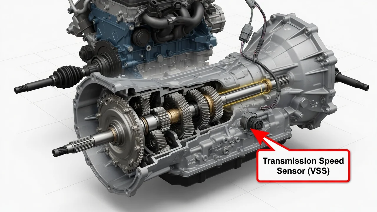
Most transmissions have at least one speed sensor, and many automatics have two: one for input speed and one for output speed. Where these sensors sit depends on the transmission type, whether the vehicle is front-, rear- or all-wheel drive, and the specific design. This guide explains where to look, how the sensors work, what changes their location, and how to approach a suspected sensor problem without replacing parts on a guess.
Where the transmission speed sensor is usually located
The transmission speed sensor is almost always mounted on the transmission case itself, with its tip reaching inside to read a rotating part. It is usually a small plastic-bodied sensor held in by a single bolt, with a wiring connector attached. On many automatics you will find two sensors. The input speed sensor, often called the turbine speed sensor, is usually toward the front of the case near the bellhousing, where it reads the speed of the shaft coming from the torque converter. The output speed sensor sits toward the rear of the transmission, where it reads the speed of the output shaft or a related gear.
On a rear-wheel-drive vehicle, the output sensor is commonly on the tailshaft or extension housing, the narrow rear section of the transmission just ahead of the driveshaft. On a front-wheel-drive transaxle, it is typically on the case near the differential or final drive area, often reachable from underneath or from the top of the transaxle after other components are moved aside. Some modern transmissions mount one or both sensors inside the case, sometimes as part of an internal wiring harness or transmission control module, which means they cannot be seen from outside at all.
How transmission speed sensors work
Each sensor faces a toothed wheel, often called a tone ring or reluctor, that turns with a shaft or gear inside the transmission. As the teeth pass the sensor tip, the sensor produces a signal whose frequency rises with rotating speed. Older and simpler designs are magnetic pickup sensors that generate their own alternating voltage, usually with two wires. Many newer designs are Hall-effect or similar active sensors that need a power supply and produce a square-wave signal, usually with three wires, though wiring varies.
The transmission control module or engine computer compares input speed with output speed to work out which gear is engaged, whether clutches are slipping, and when to command the next shift. Output speed is also frequently used to calculate vehicle speed for the speedometer, cruise control and other systems. That is why a sensor or circuit fault can affect both shift behavior and the speedometer reading at the same time.
What changes the answer for your vehicle
The biggest factor is transmission type. A conventional automatic, a continuously variable transmission, a dual-clutch unit and a manual gearbox each handle speed sensing differently. CVTs often use separate sensors on the primary and secondary pulleys. Dual-clutch transmissions may sense the speed of each input shaft. Manual transmissions usually have a single output or vehicle speed sensor, often near the rear of the case or on the transaxle near the differential, and they rely on it mainly for speedometer and engine management functions rather than shift control.
Drivetrain layout matters as well. All-wheel-drive and four-wheel-drive vehicles may place the output sensor on the transfer case rather than the transmission. Some vehicles take vehicle speed from the ABS wheel speed sensors instead of a dedicated transmission output sensor, so the sensor you are trying to find may not exist in the location you expect. Much older vehicles used a mechanical speedometer cable driven by a gear in the transmission, sometimes with an electronic sensor added to that same housing.
Even within one model, different engines or model years can use different transmissions with different sensor layouts. Knowing the exact transmission code, which is usually stamped on a tag or the case and can often be confirmed by the VIN, is the reliable way to know which sensors your vehicle has and where they are.
How to find and check the sensor yourself
Start by identifying the transmission and looking up its layout in a service manual or factory repair information for your exact vehicle. Then inspect the case with a good light. Follow the wiring harness along the transmission, look for small connectors leading to bolt-in sensors, and note their position relative to the bellhousing and the rear of the case. If you need to work underneath, park on level ground and support the vehicle on rated jack stands, never on a jack alone.
A visual check is often worthwhile before anything else. Look for a loose, corroded or oil-soaked connector, chafed wiring near exhaust or moving parts, and fluid leaking around the sensor seal. If a sensor is removed, a magnetic tip covered in fine metal debris can upset its signal, and the debris itself is worth noting because it can point to internal wear. Expect some fluid to come out when an externally mounted sensor is removed, have a new O-ring ready, and check the fluid level afterward using the procedure and fluid specification for your transmission.
When buying a replacement, confirm fitment by VIN or transmission code rather than by appearance, because input and output sensors can look similar yet have different lengths, connectors or signal types.
Symptoms and codes are not a diagnosis
Speed sensor problems are commonly associated with an erratic or dead speedometer, harsh or delayed shifts, shifting at the wrong time, cruise control that will not engage, and the transmission going into a fail-safe or limp mode. Scanning for diagnostic codes helps narrow things down. Generic codes such as P0715 point to the input or turbine speed sensor circuit, P0720 to the output speed sensor circuit, and P0500 to vehicle speed sensor issues, while manufacturers add their own specific codes.
A code or symptom indicates where the computer sees a problem, not which part has failed. The same code can come from damaged wiring, a poor connection, a damaged tone ring, metal debris, low fluid, an internal mechanical fault or a control module issue. Shift complaints in particular overlap with many other transmission problems. Testing the circuit and the sensor signal, ideally with a scan tool that shows live input and output speeds, is what separates a bad sensor from everything else. Reviewing the service history, including recent fluid changes or repairs, can also help explain what changed.
Limitations and next step
General descriptions of sensor location are a starting point, not a substitute for information about your specific vehicle. Internally mounted sensors may require removing the transmission pan, the valve body or even the transmission, and some are integrated with the control module, which can require programming after replacement. These jobs involve correct fluid refill procedures and are often better left to a transmission specialist or dealer.
If the sensor is external, easy to reach, and testing confirms it is at fault, replacement can be a reasonable owner job. If testing is inconclusive, codes return after a new sensor is installed, or shift behavior stays abnormal, have the system diagnosed professionally before spending more on parts. That keeps your repair options focused on the actual cause rather than the most likely-looking component.