Transmission Input vs. Output Speed Sensors: What Is the Difference?
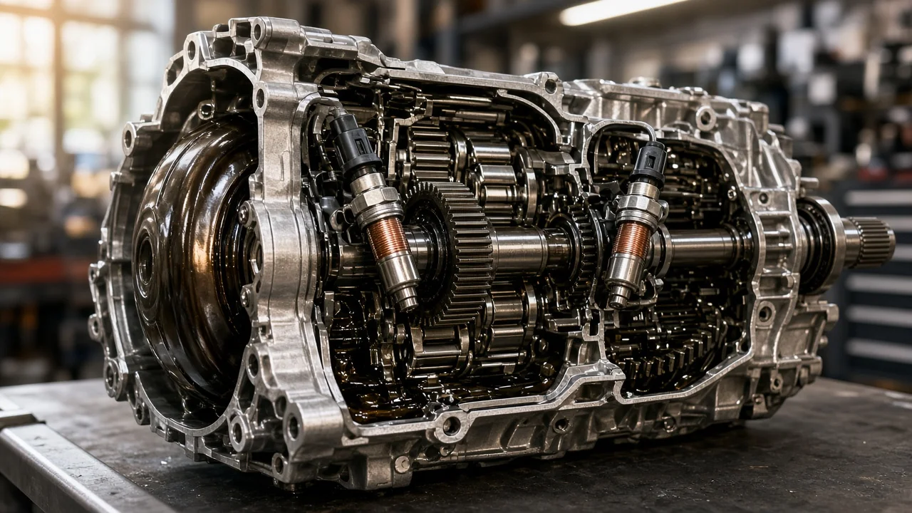
Most automatic transmissions use at least two speed sensors to decide when and how to shift. The input speed sensor reports how fast the input side of the transmission is turning. The output speed sensor reports how fast the output shaft is turning on its way to the wheels. The two often look alike, yet they feed different calculations, set different diagnostic codes and sit in different places. Knowing which is which keeps both diagnosis and parts ordering on track.
What is being compared
The input sensor is called a turbine speed sensor on many transmissions. It reads a toothed tone wheel, a clutch drum or the turbine shaft, which is the speed on the transmission side of the torque converter. The control module compares this reading with engine speed to calculate converter slip and to manage converter clutch lockup. It also compares it with output speed to work out which gear the transmission is actually in.
The output sensor reads the output shaft, the park gear or a tone ring near the rear of the transmission. Its reading follows road speed. On some vehicles it also serves as the vehicle speed sensor and drives the speedometer. Others take road speed from the ABS wheel speed sensors instead. Names are not consistent across manufacturers. You may see turbine, intermediate shaft or vehicle speed sensor, and CVTs often use primary and secondary pulley speed sensors. Some units also add a third sensor. The service information for your specific transmission defines what each sensor does, not the label on a parts box.
Compare on the same criteria
Measured component and job: the input sensor measures turbine or input shaft speed, and the output sensor measures output shaft speed. The input reading tells the module what the converter and gearsets are receiving. The output reading tells it what is leaving the transmission. Together they give the actual gear ratio, which the module checks against the gear it commanded.
Diagnostic codes: in generic OBD-II numbering, P0715 through P0718 cover the input or turbine speed sensor circuit, and P0720 through P0723 cover the output speed sensor circuit. Manufacturer-specific codes add more detail. A gear ratio code such as P0730, or one of the gear-specific codes that follow it, means the two readings disagree with the commanded gear. It does not necessarily mean either sensor has failed. Location and access: the input sensor usually sits toward the front of the case near the bellhousing. The output sensor is usually near the extension housing on rear-wheel-drive units, or near the final drive on transaxles. Many are bolted on externally and sealed with an O-ring. Others sit inside the case, on the valve body, or are built into the transmission control unit, which turns a quick swap into a pan or module job.
Symptoms: a lost input signal commonly affects shift quality and converter lockup, and it can trigger a failsafe mode. A lost output signal can cause the same problems. It may also upset the speedometer, odometer or cruise control on vehicles that use it for road speed. Signal type: either sensor may be a two-wire magnetic pickup that generates its own AC signal, or a three-wire Hall-effect sensor powered by the module. The test method therefore depends on the sensor design, not on whether it is the input or the output sensor.
Where the differences matter
Shift behavior shows the difference most clearly. Without a trustworthy input signal, the module cannot judge converter slip or how quickly clutches are applying. The result can be firm or flared shifts, no lockup at cruise, or a fixed failsafe gear. Without a trustworthy output signal, the module loses its road speed reference, so shift timing goes wrong. Upshifts and downshifts may come at odd speeds, and on some models the speedometer drops out or stability and cruise warnings appear. These patterns overlap, so the symptoms alone cannot confirm which sensor is at fault.
Operating conditions also shape how a fault shows up. Intermittent problems often appear once the case and fluid are fully warm after highway driving, or over bumps when a connector is loose. Magnetic sensors can collect fine metal debris on the tip, which weakens the signal at low speed, so stop-and-go traffic may reveal the fault first. Low fluid or worn clutches can make the ratio look wrong even when both sensors read accurately. For that reason, check fluid level and condition early, using the correct fluid specification and check procedure for that unit.
Before replacing anything, watch live scan data and compare input, output and engine speed in a steady gear. Inspect the wiring and connector pins, looking especially for chafing or heat damage near the exhaust. Test the sensor's resistance or output signal according to the service procedure, and check the tone ring for damage. Service history helps too: a recent fluid service, earlier transmission work or a sensor reused during a rebuild can all point toward a cause.
Compatibility comes first
Fitment starts with the transmission type and exact unit, identified by VIN, build code or the transmission identification tag. The same model and year can come with different transmissions. On some units the input and output sensors share a part number; on others they differ in tip length, mounting flange, connector or calibration. An input sensor installed in the output bore may bolt in and still read incorrectly, or sit close enough to strike the tone wheel.
Integrated designs narrow your options. When a sensor is part of a mechatronic unit or an internal harness, a standalone replacement may not be sold. If it is, the job may require programming or a relearn of shift adaptations afterward. Fluid lost during the repair must be replaced with the specified fluid and checked using that transmission's level procedure, which is often temperature-dependent.
Which option fits which use
Focus on the input circuit when it has a code and live data shows the input reading dropping out while output and engine speed stay steady. Focus on the output side when an output code appears together with erratic speedometer readings or shift timing. When ratio codes appear without any circuit code, rule out low fluid and internal slip before blaming either sensor. In every case, confirm the wiring and connector before buying a part.
Among repair options, an original equipment sensor matched to the VIN is usually the safest choice where tip length and calibration are critical. A reputable aftermarket part is reasonable when it matches exactly. Use a new O-ring, clean the bore and tighten the bolt to the specified torque. For internal or integrated sensors, weigh the cost of a shop that has the right scan tool for any required programming. Replace both sensors only when both are accessible and both test faulty, then clear the codes and road test to confirm the repair.