Locate the engine camshaft position sensor
The short answer
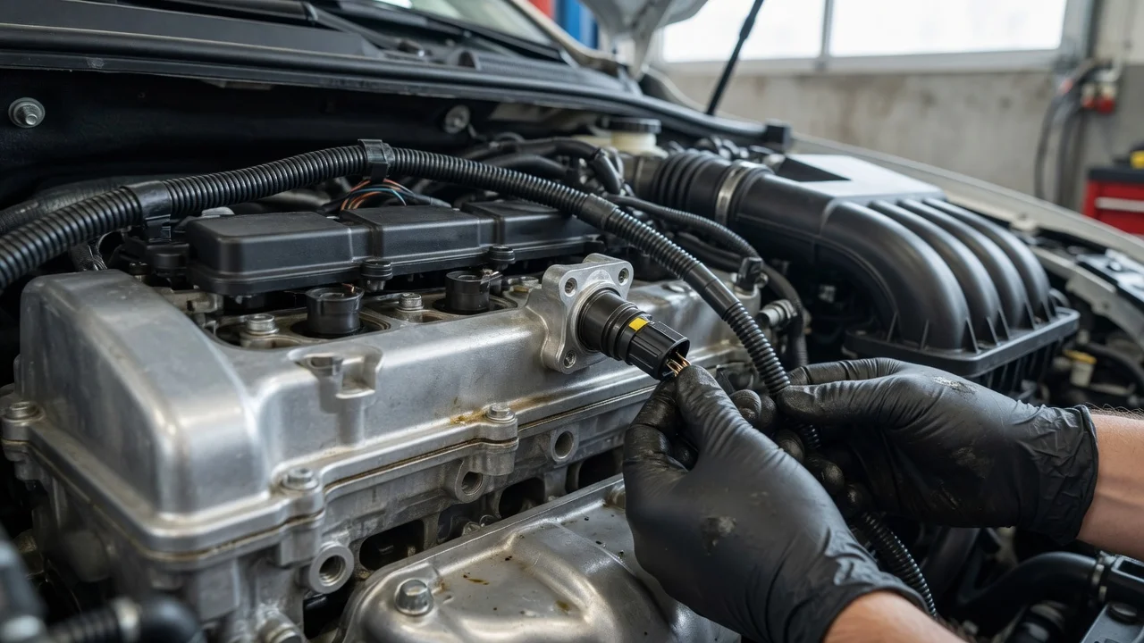
On most modern engines, the camshaft position sensor is mounted on the upper part of the engine. Common spots are the cylinder head, the valve cover or the timing cover, close to one end of a camshaft. The sensor reads a toothed wheel, a notch or a target on the camshaft or its sprocket. This tells the engine computer the camshaft's rotational position, which it uses to time fuel injection and ignition. Engines with variable valve timing also use this signal to check camshaft phasing.
The exact location depends on the engine, not just the vehicle model. The same model can use different engines across model years, generations, markets and trims, and each engine may place the sensor differently. No specific vehicle was given for this guide, so the guidance below describes general patterns only. Confirm the location for your engine in the factory service information or a repair manual for your exact vehicle configuration before you remove any parts.
Why the location varies
Engine layout: On an inline engine with one cylinder head, the sensor is usually at the front or rear of that head. A V engine has two cylinder heads, called banks, and it may have a sensor on one bank or on both. Number of camshafts: Some single overhead cam engines use one sensor. Some dual overhead cam engines use one sensor per camshaft, so a V engine with four camshafts can have up to four sensors. Timing drive design: On some engines the sensor reads a target behind the timing cover, so it is mounted on that cover rather than on the head. Older distributor ignition: On some older engines the camshaft position signal comes from inside the distributor, not from a separate sensor on the head.
How to recognize the sensor
A camshaft position sensor is usually a small plastic or plastic-and-metal body. Part of it sits inside a bore in the head or cover, and an electrical connector sticks out. It is typically held in place by a single small bolt through a mounting tab. The connector usually has two or three wires. Three-wire units are commonly Hall-effect sensors, which need a power feed, a ground and a signal wire. Two-wire units are commonly variable reluctance sensors, which are magnetic pickups that generate their own signal. Wire count is a useful hint, but it does not identify the sensor on its own.
Look near the end of a camshaft: start at the front of the cylinder head on the timing-drive end, then check the rear of the head. Follow the wiring harness: the sensor connector branches off the engine harness, often near the top or end of the head. Check the timing cover: on some engines, look on the upper portion of the timing cover near the camshaft sprockets. Remove the engine cover if fitted: many modern engines hide the top of the head under a plastic trim cover.
Parts that are easy to confuse with it
Part | Typical location | How it differs; Crankshaft position sensor | Lower on the engine, near the crankshaft pulley, on the engine block or near the transmission bellhousing | Reads crankshaft rotation rather than camshaft rotation, and usually sits low on the engine instead of on the head; Variable valve timing solenoid (oil control valve) | Often on the front of the cylinder head, near the camshafts | Controls oil flow to the cam phasers rather than sensing position; usually larger, with a cylindrical body and a two-pin connector; Coolant temperature sensor | Near the thermostat housing or a coolant passage | Threads into a coolant passage and is usually screwed in rather than bolted by a tab; Oil pressure sensor or switch | On the block or near the oil filter | Threads into an oil gallery, usually lower on the engine
The crankshaft position sensor is the part most often confused with the camshaft sensor. The two can look very similar and may even share a part design on some engines. Always confirm which sensor you are looking at against your engine's documentation.
Using trouble codes to find the right sensor
If a diagnostic trouble code led you here, the code can narrow down which sensor is involved on engines with more than one. Under the standard OBD-II numbering, P0340 refers to the camshaft position sensor A circuit on bank 1, and P0345 refers to sensor A on bank 2. Bank 1 is the side of the engine that contains cylinder 1. The letter A or B distinguishes camshafts on the same bank. A is commonly the intake camshaft or the front sensor and B the exhaust or rear one, but manufacturers apply these conventions differently. Check your engine's documentation to see which physical sensor matches the code and which side counts as bank 1.
A camshaft position code points to a problem in the sensor circuit, but it does not prove the sensor itself has failed. Wiring, connector faults or timing-related problems can produce similar codes. Diagnose the fault before replacing parts.
Before you reach for tools
Identify your exact engine using the vehicle identification number (VIN), the engine code or the owner's documentation, not just the model name. Confirm the sensor location and the number of camshaft sensors for that engine in the service information. Let the engine cool before working near the cylinder head or exhaust components. Follow the service documentation's guidance on disconnecting the battery and on whether any components must be removed for access. Note the condition of the connector and wiring as you locate the sensor, since circuit faults are a common cause of sensor-related codes.
What this guide cannot confirm
This guide does not cover any particular make, model, model year or engine. It cannot give the exact sensor position, access steps, fastener sizes or connector details for your vehicle. Those details vary by configuration and should come from documentation for your specific vehicle.