What Is a Camshaft Position Sensor Used For?
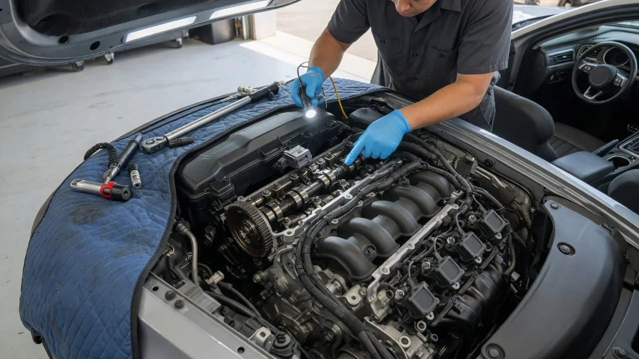
A camshaft position sensor tells the engine control module where the camshaft is in its rotation, and therefore which cylinder is approaching its power stroke. Together with the crankshaft position sensor, it lets the computer time fuel injection, spark and, on many engines, variable valve timing. This guide explains what a camshaft position sensor is used for, how its signal fits into camshaft position engine timing, and what happens when that signal goes wrong.
Position signal: what the sensor reports
In a four-stroke engine, the crankshaft turns twice for every single turn of the camshaft. That creates a problem for the engine computer. The crankshaft position sensor reports piston position and engine speed precisely, but a piston near top dead center could be finishing either its compression stroke or its exhaust stroke, and the crank signal alone cannot tell which. The camshaft position sensor resolves that ambiguity. Because the camshaft turns at half crankshaft speed and operates the valves, its position shows which phase of the cycle each cylinder is in.
Most camshaft position sensors mount in the cylinder head, timing cover or valve cover and read a toothed wheel, notched ring or machined feature on the camshaft or cam gear. Two designs are common. A Hall-effect sensor receives power from the control module and switches its output on and off as the target passes, producing a square-wave signal. A magnetic, or variable reluctance, sensor generates its own alternating voltage as the target moves past a magnet and coil. The target pattern is often deliberately uneven, with an odd tooth or gap, so the computer can recognize a reference point. Engines with multiple camshafts may use one sensor per camshaft or per cylinder bank.
The engine control module reads the cam and crank patterns together. Once it sees the expected cam reference relative to the crank teeth, it knows the engine's position within the full 720-degree cycle. This is usually called synchronization, and on many engines it happens during cranking before normal fuel and spark control begins.
Injection timing, ignition and valve timing control
Sequential fuel injection is a main reason most modern gasoline engines use a camshaft position sensor. Instead of firing several injectors at once, a sequential system opens each injector individually, timed to that cylinder's intake event. To do this, the engine control module must know which cylinder is on its intake stroke, and that comes from combining the cam and crank signals. Well-timed injection supports a smooth idle, cleaner emissions and predictable throttle response. Gasoline direct-injection engines and common-rail diesel engines also depend on accurate cylinder identification, because fuel is delivered straight into the cylinder at a specific point in the cycle.
Ignition benefits in a similar way. Engines with an individual coil for each cylinder must fire the correct coil at the correct moment, and cam-based cylinder identification makes that possible. On engines with variable valve timing, the sensor takes on another job. The control module commands a cam phaser to advance or retard the camshaft, then uses the cam signal to measure the actual cam angle relative to the crankshaft. If the measured position does not match the commanded position, the module can correct its control or record a fault. In this role the sensor acts as a feedback device, not just a reference signal.
Diagnosis: symptoms, codes and common causes
When the camshaft signal is missing, erratic or out of expected alignment, the engine control module usually turns on the check engine light and stores a diagnostic trouble code. Commonly reported symptoms include extended cranking before starting, stalling, hesitation, rough running, reduced power and sometimes a no-start condition. Exact behavior depends on the engine's software. Many systems have a fallback strategy that estimates cylinder position or uses a less precise injection mode, which may let the engine run with reduced performance. Other designs may not start without a valid cam signal. A sensor or connection that fails intermittently, for example as it heats up, can cause symptoms that come and go.
Generic OBD-II codes in the P0340 to P0349 range relate to camshaft position sensor circuits, while codes such as P0016 indicate that crankshaft and camshaft positions do not correlate as expected. Codes from P0010 to P0025 commonly involve camshaft actuator or timing control. A code points to a circuit or condition, not automatically to a failed part. The cause may be the sensor itself, damaged wiring, a corroded or loose connector, a ground or reference voltage problem, a damaged target wheel, or mechanical timing trouble such as a stretched chain, worn guide or belt that has jumped a tooth. Low or degraded oil can also affect variable valve timing systems and trigger related codes.
A sound diagnosis starts with reading all stored codes and freeze-frame data, then checking live data where the scan tool supports it, such as synchronization status or actual versus desired cam angle. Inspecting the harness and connector comes next, since wiring near hot or moving parts is vulnerable. Technicians often view cam and crank signals together on an oscilloscope to confirm the signals are present, clean and correctly aligned. Test values, pin assignments and acceptable patterns are specific to each engine, so the manufacturer's service information should guide any measurement.
Practical implications and limits
For an owner, a camshaft position sensor fault is usually a drivability problem worth addressing promptly rather than a warning light to ignore. An engine that stalls unexpectedly can leave a vehicle stranded or lose power at an awkward moment, and extended operation in a fallback mode may raise fuel consumption and emissions. A timing correlation code deserves particular caution, because the cause could be wear in the timing drive rather than an electrical fault, and on interference engines a failed timing component can allow valves and pistons to contact each other.
Replacing the sensor is a common repair, but it is not always the right one. A new sensor will not fix a stretched timing chain, a cam phaser oil supply problem or a broken wire, and the original code may return. Part quality also matters, since a sensor with different response characteristics or fitment can create new faults on some engines. After repair, certain vehicles require clearing codes, completing a drive cycle or running a relearn procedure with a scan tool, while others need nothing beyond reconnecting the sensor.
The general principles described here apply broadly, but the details do not. Sensor location, the number of sensors, target wheel patterns, fallback behavior and manufacturer-specific code definitions vary between engine families. Treat any code description or symptom list as a starting point, and confirm the details in the service manual for the exact engine before buying parts or making adjustments.