Wiring a 240V Outlet for a Home EV Charger
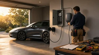
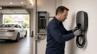
Wiring a 240V outlet for a home EV charger means running a dedicated circuit from your electrical panel to a receptacle, usually a NEMA 14-50 or NEMA 6-50, sized for the charger's continuous current draw. The short answer is that the breaker, wire gauge, receptacle and charger setting must all match each other, and the circuit must be rated at 125 percent of the charger's output because EV charging counts as a continuous load. In most US homes, that means a 40A or 50A double-pole breaker with matching copper conductors, a GFCI-protected receptacle where the adopted electrical code requires it, and a permit and inspection. Whether you should install an outlet at all, or hardwire the charger instead, depends on the charging power you want and your panel's spare capacity. This guide explains how wiring a 240 volt outlet for EV charging works, what the main choices are and where the decisions change the outcome. It is an overview for planning and for talking with an electrician, not a substitute for local code requirements or a licensed installer.
What a 240V Charging Circuit Is
Most US homes receive split-phase service: two 120V legs that together provide 240V. A standard wall outlet uses one leg plus a neutral. A 240V circuit uses both legs through a double-pole breaker, which is what allows Level 2 charging to deliver several times more power than a regular 120V outlet.
A 240V charging circuit typically includes these parts:
A double-pole breaker in the main panel or a subpanel, sized to the circuit. Two hot conductors, one from each leg of the service. An equipment grounding conductor, which provides a fault path and supports the charger's safety checks. A neutral conductor, only if the receptacle type requires one, as the NEMA 14-50 does. A receptacle rated for the circuit, or a direct hardwired connection to the charger. Ground-fault protection where the code edition adopted in your area requires it.
Most EV chargers use only the two hots and the ground. The neutral on a 14-50 is present because that receptacle was designed for appliances such as ranges and RVs that also need 120V, not because the charger uses it.
NEMA 14-50 vs NEMA 6-50
Two receptacle types dominate home EV charging. Both are rated for 50A at 240V; the difference is in conductor count and cost.
Feature | NEMA 14-50 | NEMA 6-50; Conductors | Two hots, neutral, ground | Two hots, ground; Wire needed | Four-wire cable (for example 6/3 with ground) | Three-wire cable (for example 6/2 with ground); Charger compatibility | Very common plug on portable and plug-in wall chargers; also used by RVs | Common on some plug-in wall chargers and welders; Wiring cost | Higher, because of the extra conductor | Somewhat lower; Flexibility | Broadest compatibility with plug-in chargers | Fewer chargers ship with this plug by default
If you are unsure which plug your charger uses, or you may change chargers later, the 14-50 offers broader charging compatibility. If you know your charger uses a 6-50 plug, the simpler three-wire run is a reasonable choice.
Sizing the Circuit to the Charger
The National Electrical Code treats EV charging as a continuous load, meaning it can run at full current for three hours or more. For continuous loads, the circuit must be rated at no less than 125 percent of the load. Put the other way, a charger may draw no more than 80 percent of the breaker rating. A 50A circuit supports up to 40A of charging; a 40A circuit supports up to 32A.
The table below shows commonly used pairings with copper conductors under typical residential conditions. Actual conductor sizing depends on the cable or wire type, its temperature rating, the terminal ratings on the breaker and receptacle, ambient temperature, how the cable is routed and the length of the run, so treat this as a planning reference rather than a final specification.
Charger output (continuous) | Breaker size | Commonly used copper conductor | Connection type; 16A | 20A | 12 AWG | Receptacle such as NEMA 6-20, or hardwired; 24A | 30A | 10 AWG | Receptacle such as NEMA 6-30, or hardwired; 32A | 40A | 8 AWG | NEMA 14-50 or 6-50 receptacle permitted on a 40A circuit, or hardwired; 40A | 50A | 6 AWG | NEMA 14-50 or 6-50 receptacle, or hardwired; 48A | 60A | Typically 6 AWG individual conductors in conduit, or larger cable depending on type | Hardwired only, because standard receptacles top out at 50A
Many adjustable wall chargers let the installer set the maximum current to match the circuit. The setting must never exceed 80 percent of the breaker rating. A charger left at a higher factory setting on an undersized circuit will trip the breaker at best and overheat conductors at worst.
Choosing the Wire
Wire choice depends on where the run goes and how it is installed.
NM-B cable (often called Romex) is common for runs inside finished walls, attics and joist bays. Its ampacity is based on the 60°C rating, which is why it often needs to be one size larger than individual conductors in conduit for the same breaker. Individual THHN/THWN conductors in conduit are typical for exposed runs in garages, exterior walls and outdoor installations. They can usually be rated at the 75°C column when the terminals are also rated for it, allowing a smaller gauge for the same current. UF-B cable or conductors in conduit are used for underground or wet-location runs, following burial depth and protection rules. Aluminum conductors can be used for larger feeders but require a larger gauge than copper and terminations listed for aluminum. Many receptacles and chargers are rated for copper only.
Long runs between the panel and garage can cause voltage drop, which reduces charging power and adds heat. An electrician may upsize the conductor on a long run even when the base ampacity would be adequate.
Breakers, GFCI and the Receptacle Itself
Recent editions of the National Electrical Code require GFCI protection for receptacles serving EV charging, and in many cases for garage and outdoor 240V receptacles in general. Local adoption varies, since states and municipalities adopt different code editions and amendments, so the requirement in your jurisdiction depends on which edition is in force. Where required, this usually means a 2-pole GFCI breaker in the panel.
There is a known compatibility issue: many EV chargers contain their own ground-fault detection, and stacking that with a GFCI breaker can occasionally cause nuisance tripping. This is one reason some installers and charger makers favor hardwiring, since a hardwired charger typically relies on its own built-in protection rather than an upstream GFCI. Check the charger's installation instructions for its stated requirements.
The receptacle matters more than many people expect. EV charging pushes a high current for hours, which stresses the contacts in ways an occasional-use range or dryer outlet never experiences. Inexpensive receptacles have been associated with overheating and melted faceplates under sustained charging loads. Industrial- or commercial-grade receptacles with robust contacts, terminals tightened to the specified torque and a plug that seats firmly are the practical safeguards. Repeatedly plugging and unplugging also wears contacts, so if the charger will be unplugged often, that is another point in favor of hardwiring.
Outlet or Hardwired: Which to Choose
Consideration | 240V outlet with plug-in charger | Hardwired charger; Maximum charging current | Up to 40A on a 50A circuit | Can go higher, such as 48A on a 60A circuit, if the charger and vehicle support it; Portability | Charger can be unplugged and moved or taken along | Fixed installation; GFCI | Receptacle typically requires GFCI protection under recent code | Typically no separate upstream GFCI needed, depending on charger listing; Wear points | Receptacle contacts and plug | No plug interface to wear; Outdoor use | Requires in-use weatherproof cover and suitable receptacle | Often simpler to weatherproof; Cost | Similar wiring; adds the cost of a quality receptacle and possibly a GFCI breaker | Similar wiring; avoids receptacle and possibly GFCI breaker
As an editorial judgment, a hardwired installation is usually the more robust choice for a wall-mounted charger that will stay put. A 240V outlet makes more sense when you want to use a portable charger, expect to move the charger, or are renting and want a simpler swap later.
Panel Capacity and Load Calculation
Before any wire is pulled, the panel needs room for a double-pole breaker and the service needs enough capacity for the added load. A 40A or 48A charger running for hours is one of the largest loads a home can have, comparable to or larger than an electric range or central air conditioner.
An electrician performs a load calculation based on the home's service size and existing appliances to determine whether the new circuit fits. If capacity is tight, options include setting the charger to a lower current, adding a load management device that reduces or pauses charging when other large loads run, or upgrading the service. Some chargers support power sharing between two units on one circuit, useful for two-EV households. A full panel without open spaces may need a subpanel or panel replacement, which changes the project scope significantly.
What the Installation Involves
At a high level, a typical installation follows this sequence. Specific methods depend on the home, the panel and local code.
Confirm the charger model, its plug type or hardwire requirement, and its maximum current. Verify panel space and service capacity through a load calculation. Pull a permit where the jurisdiction requires one, which is common for new 240V circuits. Plan the route from the panel to the charging location, choosing cable or conduit based on the environment. Install the correctly sized double-pole breaker, GFCI type if required. Run the conductors, secure and protect them, and make terminations to the specified torque. Mount the receptacle in a suitable box with the correct cover, or connect the charger directly. Set the charger's maximum current to no more than 80 percent of the breaker rating. Test the circuit and have it inspected before regular use.
Working inside a live service panel carries serious shock and arc-flash risk, and errors in conductor sizing or terminations can create a fire hazard that may not appear until the circuit has been loaded for hours. Some jurisdictions allow homeowners to do their own electrical work with a permit; others restrict it. Unpermitted work can also complicate insurance claims and home sales. For most people, a licensed electrician is the appropriate route.
How the Vehicle Affects the Decision
The circuit sets the maximum the wall can supply, but the vehicle decides how much it will accept. Every EV has an onboard charger that converts AC from the wall into DC for the battery, and its rating caps Level 2 charging speed. This rating varies by make, model, model year and sometimes trim or battery option, so check the vehicle specification for your exact car. Installing a 60A circuit for a car whose onboard charger accepts only around 32A adds cost without adding speed, though it may future-proof the installation for a later vehicle.
The vehicle's battery management and thermal management systems also shape the session. The car may reduce charging current when the battery is very cold, very hot or near full, so actual charging power is often below the circuit's maximum. These systems work independently of the home wiring, but they explain why a correctly installed circuit does not always deliver its rated output.
Before current flows, the charger and car perform a handshake: the charger checks for a proper ground and communicates the available current, and the vehicle confirms isolation between its high-voltage system and the chassis. A missing or poor ground connection is a common reason a newly wired outlet fails to start charging.
Common Mistakes to Avoid
Sizing the circuit to the charger's full output instead of applying the 125 percent continuous-load rule. Using wire rated for the 75°C column when the cable type or terminals are limited to 60°C. Installing a low-cost receptacle that is not designed for sustained high current. Leaving an adjustable charger at a setting higher than the circuit allows. Using an extension cord or adapter between the charger and a 240V outlet. Repurposing an existing dryer or range circuit without confirming its rating, receptacle type and that it is not shared. Skipping the permit and inspection.
Next Steps
Start with three facts: your vehicle's onboard charger rating, the charger you plan to use and whether it plugs in or hardwires, and your electrical panel's service size and open breaker spaces. With those in hand, an electrician can perform a load calculation, recommend a circuit size and quote the job. For a typical setup, a 50A circuit feeding either a quality 14-50 receptacle or a hardwired charger set to 40A covers the needs of most current EVs, while a hardwired 60A circuit is worth considering only if both your charger and vehicle can use the extra power.