Toyota Brake Proportioning Valve Diagram Guide
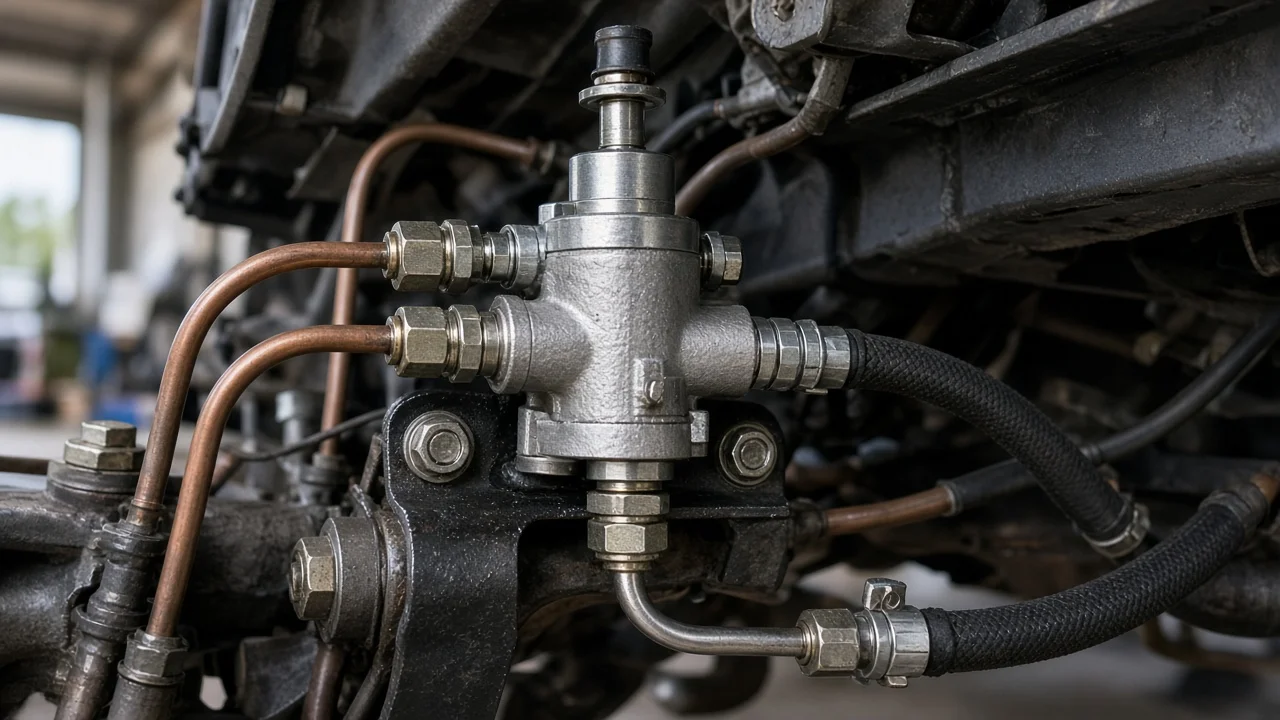
A Toyota brake proportioning valve diagram shows how brake fluid travels from the master cylinder to the front and rear brakes, and where the valve that limits rear pressure sits in that path. The layout depends on the model, drivetrain and whether the vehicle uses a mechanical valve or electronic brake force distribution. This guide explains how to read such a diagram, which configurations change it and what an owner can sensibly check.
What a Toyota Proportioning Valve Diagram Shows
There is no single diagram that fits every Toyota. On models with a conventional mechanical valve, the drawing typically shows the master cylinder with its two outlet circuits, steel lines running to the proportioning valve, and outlet lines continuing to the rear brakes. Front circuits either bypass the valve or pass through an unrestricted section of the same body. On many Toyota pickups and SUVs with a leaf-spring rear axle, the diagram instead shows a load sensing proportioning valve, which Toyota calls the LSPV, mounted on the frame near the rear axle and connected to the axle housing by a lever, spring and linkage.
Many newer Toyotas with ABS have no separate mechanical valve at all. Their hydraulic diagram routes the lines through the ABS actuator, and rear pressure is controlled electronically. For your exact vehicle, the factory repair manual's brake section is the dependable reference: it identifies each port, shows line routing and contains any adjustment or bleeding procedure. A generic drawing is useful for understanding the system but should never be used to set an LSPV or reroute lines.
How the Proportioning Valve Works
During hard braking, weight shifts toward the front of the vehicle. The front tires gain grip while the rear tires lose some. If the rear brakes received the same pressure as the fronts, the rear wheels could lock early and make the vehicle unstable. A proportioning valve prevents this by passing full pressure to the rear brakes up to a set point, often called the split point. Above that point, a spring-loaded piston inside the valve allows rear pressure to rise more slowly than master cylinder output, so the rear contributes less of the total braking as stopping force increases.
A load sensing valve adds one more input. When cargo or a trailer loads the rear axle, the distance between the frame and the axle changes. The linkage moves the valve lever, which changes the spring force acting on the piston and raises the split point. A loaded truck therefore gets more rear braking, while an empty one gets less. That is why the linkage on an LSPV diagram matters as much as the brake lines. Electronic brake force distribution performs a similar job using wheel speed sensors and valves inside the ABS actuator rather than a mechanical spring.
Configurations That Change the Diagram
The hydraulic split is the first major difference. Many rear-wheel-drive trucks use a front and rear split, where one master cylinder circuit feeds the front brakes and the other feeds the rear, so a single rear valve can manage rear pressure. Many front-wheel-drive cars use a diagonal split, where each circuit feeds one front wheel and the opposite rear wheel. In a diagonal system with mechanical proportioning, both rear outputs need control, so the diagram may show a dual valve or valves built into or mounted at the master cylinder ports.
Other details also change the picture. ABS and non-ABS versions of the same model can route lines differently. Rear drum brakes use wheel cylinders, while rear discs use a caliper at each wheel. Cab style, bed length, two-wheel or four-wheel drive and trim level can affect valve location or calibration. Suspension changes matter on LSPV models: lift kits, lowering kits, replacement leaf springs or overload springs alter ride height and lever position, which shifts rear braking behavior. Confirm vehicle fitment with VIN-specific service information before ordering parts or comparing diagrams.
What You Can Check as an Owner
Several checks need no disassembly. Locate the valve using the manual, then look for wetness at the valve body, fittings and nearby lines, and for heavy corrosion on steel lines. On LSPV models, confirm the linkage is connected, the spring is intact, the lever moves rather than being seized, the bushings are not broken and the axle bracket is not bent. Check the brake fluid level and condition at the reservoir. A gradually falling level can reflect normal pad wear, while a sudden drop suggests a leak.
Some symptoms can point toward proportioning: rear wheels locking early, especially on an empty truck on a wet road, or weak rear braking, where front brake pads wear quickly while rear pads or shoes last unusually long. These signs overlap with more common causes, including contaminated friction material, a sticking caliper or seized slide pins, misadjusted drum brakes, worn brake rotors, mismatched tires and ABS faults. Inspect the basics first, comparing pad and shoe thickness with the wear limits in the manual and checking rotor and drum condition.
Avoid adjusting or prying the LSPV lever, disconnecting the linkage to change pedal feel, or fitting an aftermarket adjustable valve as a guess. Some valves have their own bleeder and model-specific bleeding steps, so follow the manual and use the fluid type marked on the reservoir cap.
Limitations and Next Step
This explanation is general. Split points, LSPV adjustment dimensions, torque values and bleeding order vary by model and appear only in factory service information, so none are given here. Mechanical proportioning valves are usually replaced rather than rebuilt, and correct setup can require precise measurement and sometimes pressure gauges at the front and rear circuits to confirm the valve is working as designed.
Stop driving and arrange professional service if the pedal feels soft or sinks toward the floor, the brake warning light stays on, fluid is leaking, the vehicle pulls hard or the rear slides under braking. On vehicles with electronic brake force distribution, the brake and ABS warning lights illuminated together can indicate the system is not managing rear pressure correctly. In every case, the next step is to obtain the VIN-specific brake diagram and procedures, complete the basic inspection, and have a qualified brake technician verify any suspected valve fault.