Rear ABS Tone Ring Replacement: A Practical Guide for Vehicle Owners
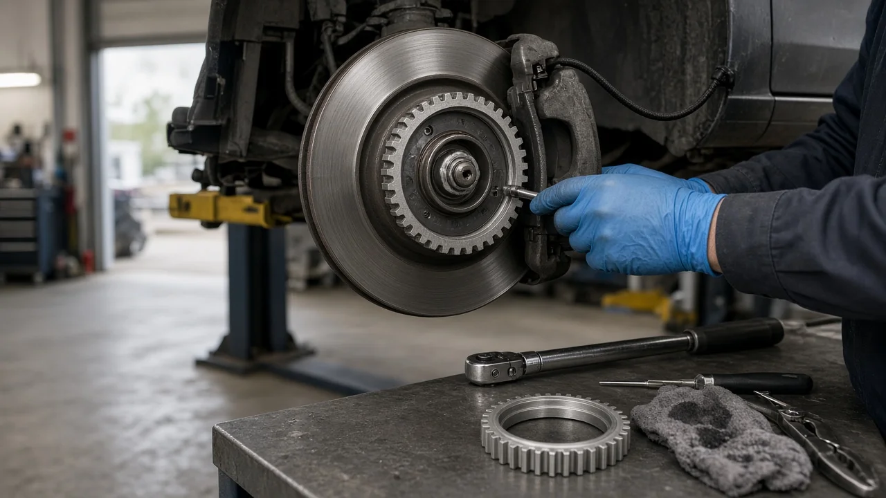
A rear ABS tone ring, also called a reluctor ring, gives the wheel speed sensor a pattern of teeth or magnetic poles to read. When it cracks, rusts or loses teeth, the ABS module receives an erratic signal and may disable anti-lock braking and stability control. Replacing the ring can be simple or involved depending on how your vehicle carries it, so this guide covers confirming the fault, preparing, removing, installing and checking the work.
Confirm the part and repair scope
Start by proving the ring is the problem. An ABS warning light with a rear wheel speed sensor code can be caused by the sensor, its wiring, a corroded connector, excessive wheel bearing play or the ring itself. A scan tool that shows live wheel speed data is the most useful check: drive slowly and compare the four readings. A rear channel that drops out, spikes or reads erratically while the others stay smooth points toward that corner. Then inspect the ring with the wheel off, rotating it slowly. Look for cracks, a ring that has split from rust swelling underneath it, missing or damaged teeth, debris packed between the teeth, or a ring that wobbles on its seat.
Next, confirm vehicle fitment and what the ring is attached to, because that decides the whole job. On many solid rear axles the ring is pressed onto the axle shaft near the bearing. On independent rear suspension it may be pressed onto the outer CV joint housing or the hub. Some rear rotors and drums carry an integral ring, so the rotor or drum is replaced instead. Many newer vehicles use a magnetic encoder built into the wheel bearing seal, which is not serviced separately; the bearing or hub assembly becomes the replacement part. Match the new ring by year, model, drivetrain and tooth count using the service information or parts catalog for your exact vehicle. A ring with the wrong tooth count produces an incorrect speed signal even when it looks identical.
Prepare tools and safe access
Get the factory service procedure for your vehicle before you begin. It specifies the removal path, any special tools, the ring seating position, the sensor air gap where it is adjustable, and torque values for caliper brackets, axle nuts and lug nuts. Do not substitute guessed numbers; brake and hub fasteners depend on correct torque.
Typical tools include a scan tool with ABS live data, wheel chocks, a floor jack and rated jack stands, a torque wrench, basic hand tools, penetrating oil, a wire brush or abrasive pad, and whatever the ring itself requires: a bearing puller, a hydraulic press, or an installer driver sized to push on the ring body rather than the teeth. Work on level, solid ground, chock the front wheels, and support the vehicle on stands at the specified lift points, never on the jack alone. Because the rear wheels must turn and the drum or rotor may need to come off, release the parking brake only after the vehicle is secured.
Be honest about the scope. Replacing an integral rotor or bolting on a hub assembly is within reach of an experienced owner. Pulling a rear axle shaft from a solid axle means opening the differential, removing retaining clips or bearing retainers, and refilling gear oil to specification. Pressing a ring onto a CV joint or hub requires a press and proper adapters. If you lack the equipment or experience, a brake or driveline shop is the safer choice.
Remove without avoidable damage
Loosen the lug nuts, raise and support the vehicle, and remove the wheel. Unplug and remove the wheel speed sensor first if the procedure allows it. Sensors often seize in their bores; soak them with penetrating oil and work them out gently rather than prying on the tip, and keep the sensor clean once it is out. Removing it early prevents the sensor tip from being struck while you pull or split the old ring.
Remove the caliper and caliper bracket, and hang the caliper from the suspension with wire or a hook so its weight never pulls on the flexible brake hose. Leave the hose connected; there is no need to open the hydraulic system, so the brake fluid stays sealed and no bleeding is required. Do not press the brake pedal while the caliper is off. Remove the rotor or drum, noting the parking brake shoe and cable arrangement on drum-in-hat designs. From here, follow the path for your design: axle shaft removal, CV axle or hub removal, or unbolting a hub assembly.
A pressed ring is usually removed with a puller or press, or by carefully splitting it along its body when the service procedure allows. Never cut or chisel into the shaft, CV housing or bearing seat beneath it; a nick there can weaken the part or leave the new ring sitting crooked. Once the old ring is off, clean rust and scale from the seat so the replacement can sit square, and keep grinding dust and metal chips away from bearings, seals and magnetic encoders.
Install and restore the system
Check orientation before pressing. Some rings have a chamfer or inner step that must face a particular direction, and magnetic encoders have an active side that must face the sensor. Press the ring evenly with a driver or press adapter that bears on the ring body, never on the teeth, and stop at the seated position or depth given in the service information. Do not hammer it on unevenly, and do not apply heat unless the procedure calls for it, because heat can damage nearby seals and bearings. A correctly installed ring sits square with no visible wobble when the shaft or hub turns.
Reassemble in reverse order: axle shaft, CV axle or hub, rotor or drum, parking brake components, caliper bracket and caliper, torquing each fastener to its specified value. While everything is apart, check the brake pads for remaining friction material against the manufacturer's wear limits, and inspect the brake rotors for scoring, heat cracks or a pronounced outer lip that suggests they are near minimum thickness. If you opened the axle, refill it with the correct gear oil to the specified level.
Clean the sensor tip and bore, install the sensor fully seated, and set the air gap if your vehicle uses an adjustable sensor. Route the harness through its original clips away from the axle, suspension and exhaust, and make sure the connector locks. Mount the wheel, torque the lug nuts to specification, and pump the brake pedal several times before moving the vehicle until it feels firm. Clear the stored ABS codes with the scan tool; most vehicles need no further calibration after this repair, but follow any relearn or initialization step listed for your model.
Check the completed work
With the scan tool connected, drive slowly in a safe, open area and watch the wheel speed readings. All four should rise and fall together smoothly, and the repaired corner should no longer drop out or spike. The ABS warning light should go out after the system self-test, which on many vehicles completes once the car reaches a low road speed. Make several normal stops and confirm the pedal feels firm, the vehicle stops straight, and no grinding or rubbing comes from the rear.
If the ABS light or code returns, recheck the sensor connector, wiring and air gap, confirm the ring is fully seated and square, check for wheel bearing play, and verify the replacement ring's tooth count. A red brake warning light, a low or soft pedal, fluid leaking near the caliper, or pulling under braking is a different problem: stop driving the vehicle and have the braking system inspected by a professional before further use. Recheck lug nut torque after a short distance if your service information recommends it.