Why Do Some Car Sensors Have Three Wires? Power, Ground and Signal Explained
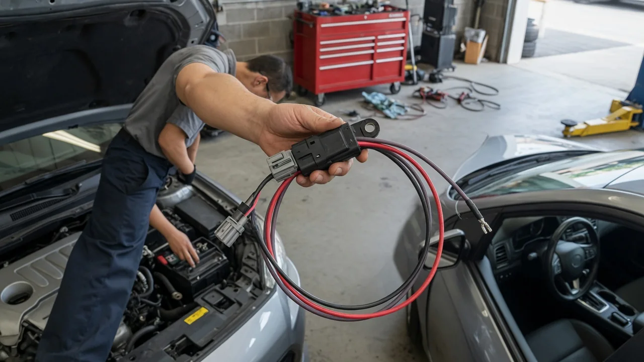
Look at the connector on a throttle position sensor, a manifold pressure sensor or many crankshaft and camshaft position sensors, and you will often find three wires. That three wire automotive sensor layout is not arbitrary. Each conductor has its own job: one supplies power, one provides a ground return, and one carries the measurement back to the engine control module. Knowing why some car sensors have three wires makes wiring diagrams easier to read and fault codes easier to interpret.
Power: Why the Sensor Needs a Supply Wire
Not every sensor needs its own power feed. A thermistor-type coolant temperature sensor is passive: the control module sends a voltage through an internal resistor, and the sensor simply changes resistance with temperature, so two wires are enough. A variable reluctance sensor generates its own alternating voltage as a toothed wheel passes it, so it also works with two wires. A third wire becomes necessary when the sensor contains something that must be energized, such as a potentiometer, a Hall-effect circuit or a pressure-sensing element with built-in signal conditioning electronics.
On many vehicles, that supply is a regulated reference voltage produced by the control module, commonly 5 volts, rather than raw battery voltage. Battery voltage rises and falls with cranking, charging and electrical loads, which would make a sensor's output harder to interpret. A stable reference gives the module a known starting point. Some sensors, including certain Hall-effect position sensors, are instead fed from an ignition-switched or battery circuit. Which approach a given vehicle uses depends on the design, so the wiring diagram for that vehicle is the authority.
Many reference-fed sensors work ratiometrically, meaning their output is a proportion of the supply rather than a fixed value. Because the module knows the reference it is providing, small shifts in that reference tend to cancel out in the calculation. The reference circuit is also frequently shared by several sensors inside the module. If one sensor or its wiring shorts the reference to ground, the shared supply can be pulled down, and multiple unrelated-looking sensors may report faults at the same time.
Ground: The Return Path That Completes the Circuit
Current that flows into a sensor has to return somewhere. In many three-wire designs, the return is a dedicated sensor ground, sometimes labeled signal return or low reference, that runs back to the control module instead of bolting to the nearest body panel. The reason is accuracy. The module measures the signal relative to its own ground. If the sensor were grounded to the chassis at a different point, any voltage difference between those two grounds would be added to or subtracted from the reading, and the module would have no way to tell.
Ground problems are easy to underestimate. Corrosion, a loose terminal or a damaged conductor adds resistance, and resistance with current flowing through it creates a voltage drop. When a sensor works within a few volts, even a fraction of a volt of ground offset is a meaningful share of the signal range. A sensor whose ground sits slightly above the module's ground can report a value that is consistently skewed, while a completely open ground can drive the signal toward an extreme or make it erratic. Like reference circuits, sensor grounds are often spliced together, so one bad splice can affect several sensors at once.
Signal: How the Measurement Reaches the Module
The third wire carries the information the module actually wants. That information generally arrives in one of two forms. Analog sensors, such as many throttle position and manifold pressure sensors, produce a voltage that varies continuously between a low value and a high value within the reference range. Digital-style sensors, such as many Hall-effect crankshaft and camshaft sensors, switch between two states, and the module cares about the timing and frequency of those pulses rather than the exact voltage level.
Analog sensors are usually designed so their normal output stays inside a band rather than touching zero or the full reference voltage. That gap is deliberate. It lets the module tell a genuine reading from a wiring fault. A signal stuck near zero can point to a short to ground or a missing supply, while a signal stuck near the reference can point to an open ground or a short to the reference circuit. This logic is the basis for many circuit low and circuit high diagnostic trouble codes.
Some Hall-effect sensors use an open-collector output. In that arrangement, the sensor pulls the signal line to ground to create the low state, while a pull-up resistor, often inside the control module, creates the high state. As a result, measuring the signal wire with the sensor unplugged may still show voltage coming from the module, which is normal for that design. Some newer sensors also send digital data over the signal wire using serial formats, and a basic voltmeter cannot decode those messages meaningfully.
Practical Implications and Limits
The three-wire structure suggests a logical diagnostic order. Confirm the supply is present with the key on, confirm the ground is sound, and only then judge the signal while the sensor is operating. Checking supply and ground first helps avoid replacing a sensor that was never the problem. A voltage drop test on the ground with the circuit active is generally more revealing than a resistance check on a disconnected wire, because a damaged conductor can pass an ohmmeter test yet fail under load. Watching the signal on a scan tool while back-probing the connector lets you compare what the module reports with what is actually present at the sensor.
There are limits to what the wire count tells you. Three wires does not reveal the sensor type, its supply voltage or its expected output range, and wire colors and pin positions differ between manufacturers and sometimes between model years of the same vehicle. Not every three-wire part follows the power, ground and signal pattern either. Some heated oxygen sensors, for example, use two wires for the heater and one for the signal, grounding the sensing element through the exhaust. Vehicle-specific service information is the reliable source for pinouts and values.
Test methods matter as much as test results. Piercing wire insulation can let moisture in and start corrosion that causes a future fault, so back-probing at the connector is usually preferable. Incandescent test lights draw enough current to stress some module circuits, so a high-impedance meter is the safer tool on sensor wiring. Never connect a reference or signal wire to battery voltage, because doing so can damage the sensor or the control module.