What Is an Automotive Ground Point? How Vehicle Grounds Work and How to Inspect Them
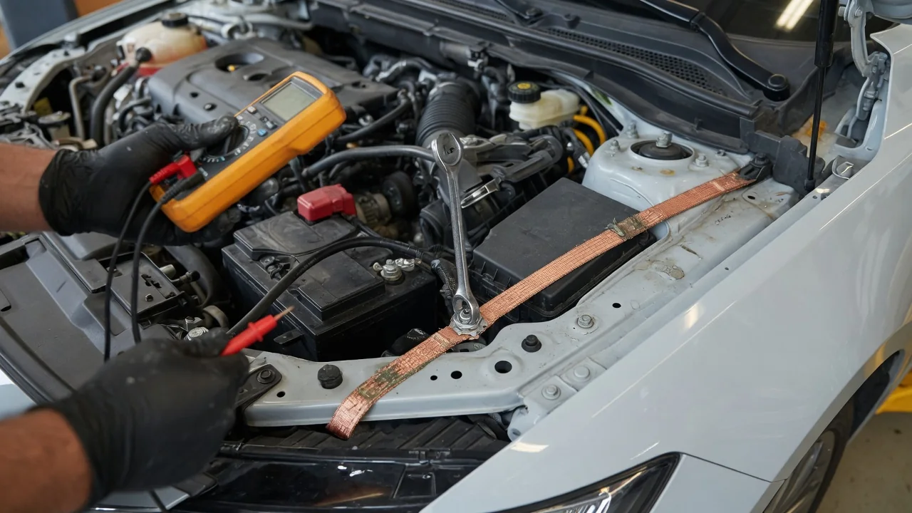
An automotive ground point is a designated spot where one or more ground wires are fastened to a vehicle's metal structure, such as the body, frame, or engine, so electrical current can return to the battery's negative terminal. Most vehicles use their metal structure as a shared return path, so these small connections affect nearly every low-voltage circuit. This guide explains how the return path works, why several wires often share one ground point, and how ground points are inspected.
Circuit Return: How a Ground Point Completes the Path
Every electrical circuit needs a complete loop. Current leaves the positive battery terminal, passes through a fuse, switch, or relay and the supply wiring, powers a load such as a lamp, motor, or control module, and then must travel back to the negative battery terminal. Running a separate return wire from every device all the way to the battery would add a large amount of copper and complexity. Instead, many vehicle designs treat the metal body, chassis, and engine as one large common conductor. The battery negative cable connects to that structure, and individual circuits connect to it at ground points. A vehicle chassis ground point is therefore the place where a circuit's return wire hands its current off to the structure for the trip back to the battery.
Physically, a ground point is usually simple. A ring terminal or eyelet crimped onto the end of a ground wire is held against bare metal by a bolt, screw, nut, or welded stud. Some designs use serrated or toothed washers that bite through surface films to improve contact. The mating surface must be free of paint, sealer, and heavy corrosion, because those materials resist current flow. Ground points can be found in the engine compartment, behind interior trim panels, under seats, in the trunk or cargo area, and on the engine or transmission. Because the engine sits on rubber mounts that do not conduct well, a ground cable or braided strap typically links the engine to the body. Exact locations differ from vehicle to vehicle, and wiring diagrams in the service information usually identify each one.
Not every circuit relies on the chassis for its return. Some sensors and electronic components use a dedicated ground or signal return wire that runs back to their control module. This keeps the low-voltage reference used for measurements separate from the electrical noise and voltage fluctuations that heavy loads can create on the body. Whether a given circuit uses a chassis ground, a dedicated return, or both is a vehicle-specific design decision.
Multiple Wires: Why Several Circuits Share One Ground Point
It is common to find several ring terminals stacked on a single bolt, one terminal crimped to multiple wires, or a harness splice that merges the grounds of several components into a single wire leading to one ground point. Grouping grounds this way reduces the number of holes and fasteners in the body, simplifies harness routing, and lets designers collect the returns of nearby components, such as the lamps in one corner of the vehicle, at a convenient location.
The trade-off is that a shared ground point becomes a shared point of failure. If that connection loosens or corrodes, every circuit attached to it can be affected at the same time, producing symptoms that seem unrelated: dim or flickering lights, erratic gauges, intermittent accessories, communication faults between modules, or unexpected warning lights. When current cannot return easily through its intended ground, it may find an alternate path through other components that share the connection. This is sometimes called backfeed, and it can cause effects such as a lamp glowing faintly when a different circuit is switched on.
Ground wire size follows the current it must carry. The main battery-to-engine and engine-to-body connections are heavy cables or straps because they handle starter current, while grounds for small lamps and modules use much thinner wire. When several terminals share a fastener, the stacking order, hardware, and tightness can matter, and service information may specify them. Adding an aftermarket accessory ground to an existing point also adds current through that connection, so it should be done with the original design in mind.
Inspection: Checking an Automotive Ground Point
A visual inspection starts with finding the ground point, ideally using the wiring diagram or ground distribution information for the specific vehicle. Look for a loose or missing fastener, green or white corrosion on copper terminals, rust under the terminal, broken wire strands, a cracked or loose crimp, melted insulation, and heat discoloration. Ground points in areas exposed to water, road spray, or salt deserve particular attention. Also check whether paint, undercoating, or sealer has ended up between the terminal and the metal, which can happen after body repairs.
An ohmmeter check on a de-energized circuit can confirm continuity, but it has a limitation: a connection held together by a few strands or a thin corroded contact may pass that test yet fail once real current flows. A voltage drop test addresses this. With the circuit switched on and operating, a voltmeter is connected with one lead on the battery negative post itself, not the cable clamp, and the other lead on the component's ground terminal or the ground point. The reading shows how much voltage is being lost along the return path. The acceptable limit depends on the circuit and should come from the vehicle's service information. If the reading is too high, moving the probe to intermediate points, such as the terminal, the fastener, and the bare metal next to it, helps isolate where the resistance is.
Typical repair involves removing the fastener, cleaning the terminal and the mounting surface to bright metal, reinstalling with the correct hardware, and tightening it properly without stripping threads in thin sheet metal. Some manufacturers recommend a protective coating over the finished joint. A terminal or wire that is cracked, heat-damaged, or badly corroded is better replaced than cleaned. Disconnecting the battery before working on grounds is a common precaution, though on some vehicles it can reset stored settings, so the service procedure should be followed.
Practical Implications and Limits
Because one weak ground can disturb several systems at once, ground connections are a sensible early check when electrical symptoms appear across seemingly unrelated components. They are also worth confirming after work that disturbs them, such as collision or body repair, engine or transmission removal, battery replacement, or accessory installation, since a ground left off, painted over, or under-tightened can create problems that only show up later under load or after exposure to moisture.
There are limits to what a ground point check can tell you. A clean-looking connection can still have high resistance, and a corroded-looking one may still carry current adequately, which is why measurement under load is more reliable than appearance alone. Restoring a good ground will not repair a failed module, a broken supply wire, or a faulty switch elsewhere in the circuit. Designs also vary: the number and placement of ground points, the use of dedicated signal grounds, and the materials involved differ between vehicles. Where aluminum or composite structures meet steel or copper, manufacturers may use specific hardware or methods to manage corrosion between dissimilar metals.
This explanation applies to the conventional low-voltage electrical system. The high-voltage systems in hybrid and electric vehicles are generally designed to be isolated from the chassis and follow different rules, and working on them requires appropriate training and procedures. For exact ground locations, tightening values, and approved repair methods on a particular vehicle, the manufacturer's service information remains the authoritative reference.