Why Are Some Car Sensors Heated? Temperature, Power and Faults
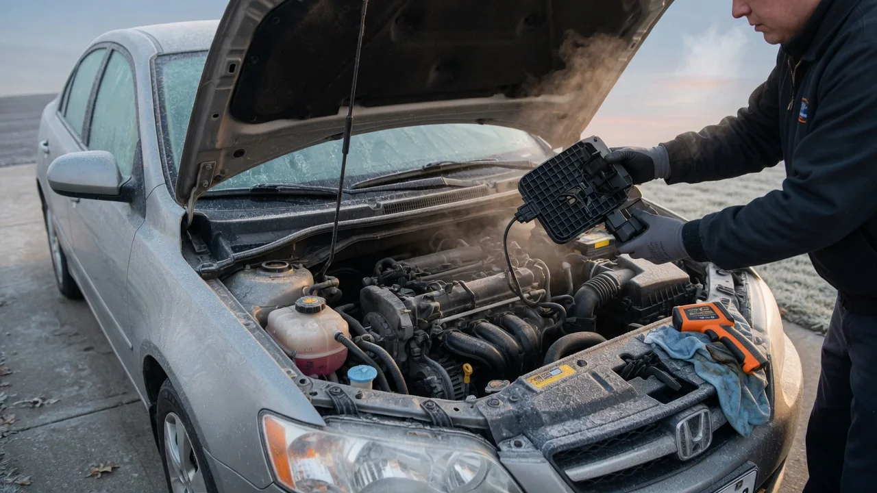
Several sensors in a modern car cannot do their job until they are hot, so manufacturers build electric heaters into them. The best-known examples are the oxygen and air-fuel ratio sensors in the exhaust, but the same idea appears in other heated automotive sensors. It helps to know why these parts are heated, how the heater gets its power, and what happens when the heater fails. That knowledge makes warning lights and diagnostic trouble codes much easier to interpret.
Operating temperature
The ceramic element in a conventional oxygen sensor is usually made of zirconia. It only conducts oxygen ions and produces a usable signal once it reaches a high temperature, typically several hundred degrees. Below that point the output is weak, slow or meaningless. Early sensors relied entirely on exhaust heat, so the engine control module had to run in open loop, using preset fuel tables, until the exhaust warmed the sensor. That could take minutes, particularly at idle or in cold weather, and emissions were higher during that period.
An internal heater solves this problem. It brings the element up to temperature quickly after start-up and holds it there regardless of exhaust conditions. It also lets the sensor be mounted farther from the engine, such as downstream of the catalytic converter, where exhaust gas alone may not keep it hot enough during idling or light cruising. Wide-band air-fuel ratio sensors, NOx sensors and particulate matter sensors work on the same principle. Their accuracy depends even more on a stable, tightly controlled element temperature.
Not every heated sensor is heated for the same reason. In a hot-wire or hot-film mass airflow sensor, heating is the measuring principle itself. The electronics track how much current is needed to keep the element above intake air temperature as air flows across it. On some vehicles, heaters are also built into camera or radar mounting areas to keep ice and condensation off the sensing path. In every case, the sensor needs a controlled thermal condition to deliver a trustworthy signal.
Electrical power
A sensor heater is a resistive element embedded in or next to the sensing ceramic. It is electrically separate from the signal circuit, which is why a heated oxygen sensor typically has more wires than an unheated one: two of them are dedicated to the heater. Power usually comes from battery voltage through a fuse, often via a relay or an ignition-switched feed, so the heater only operates with the ignition on. The exact wiring layout, fuse location and wire colors vary by vehicle and must be taken from the service information for that model.
On most modern systems, the engine control module controls the heater rather than simply switching it fully on. It commonly does this on the ground side, using pulse-width modulation to vary the average power. Full power may be applied after start-up to warm the element quickly, then reduced once the sensor is hot or the exhaust is supplying enough heat. Some systems deliberately delay or limit heating right after a cold start, because water condensed in the exhaust can strike a hot ceramic element and crack it. Many control modules also monitor heater current or estimate element temperature from its internal resistance. This lets them detect heater problems and keep the temperature within a narrow window.
The heater draws noticeably more current than the sensor signal circuit, so it is the part of the sensor most affected by supply problems. A weak connection, a corroded terminal or a poor ground can reduce heater power without affecting anything else. The control module may then report it as a heater performance fault.
Faults
The most common heater fault is an open circuit inside the sensor, where the heating element itself has burned out or cracked. Other causes include a blown fuse, a failed relay, wiring damaged by nearby hot exhaust components, chafed harnesses and contaminated or corroded connectors. Less often, a driver circuit inside the control module fails. Several heated sensors can share one fuse, so a single short can disable more than one heater at the same time.
When the control module detects a heater problem, it usually stores a diagnostic trouble code and turns on the malfunction indicator lamp. Generic powertrain codes for oxygen sensor heaters include P0135 and P0141, along with others in the P0030 to P0064 range. The specific code indicates the bank and sensor position, and manufacturer-specific codes may also be used. Typical effects include delayed closed-loop fuel control after a cold start and incomplete emissions readiness monitors. A faulty upstream heater can also change fuel trim behavior. A failed downstream heater mainly affects catalyst monitoring rather than drivability.
Diagnosis follows the circuit. A technician typically confirms supply voltage at the sensor connector with the ignition on and checks the ground or control side. They then measure heater resistance across the sensor's heater terminals and compare the result with the specification in the service manual. An open element points to the sensor. A good element with missing power or control points to the wiring, the fuse or the module. A heater code alone does not prove that the sensor's signal portion has failed, and a signal code does not automatically mean the heater is at fault.
Practical implications and limits
For owners, heater design matters most during cold starts and short trips. A working heater lets the engine reach closed-loop control sooner, which supports efficient fuel delivery and lower emissions in the first minutes of driving. A car with a failed heater may run normally once fully warm, so the fault can seem harmless. It can still keep a vehicle from passing an emissions inspection that relies on readiness monitors.
A replacement heated sensor must match the original design, including heater type, connector and wire count. Fitting a sensor with a different heater, or splicing in a universal unit without following the correct procedure, can cause wrong heater current, new codes or poor sensor performance. Some failures come from wiring or fuses, so it makes sense to confirm the circuit before buying a new part. A blown fuse deserves particular attention, because it often indicates a short that will blow the new fuse too.
General explanations also have limits. Heater control strategies, warm-up timing, the conditions that set a heater fault and even which sensors are heated vary between manufacturers, engines and model years. General principles explain why heating exists and how faults usually appear. Test values, wiring diagrams and repair steps should always come from the service information for the specific vehicle.