Understanding a Glow Plug Relay Wiring Diagram
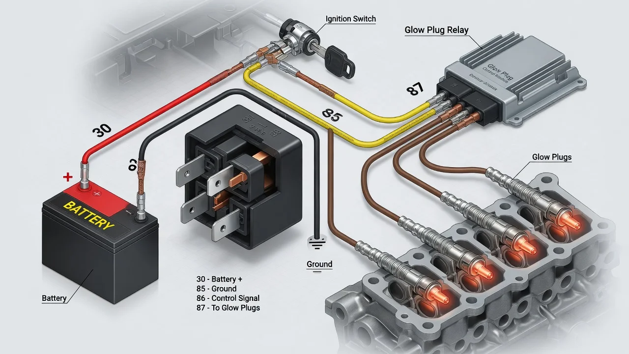
A glow plug relay wiring diagram shows how a diesel engine's preheating circuit gets battery power to the glow plugs and what switches that power on and off. Reading it correctly helps you trace a hard-start or no-glow complaint without guessing. This guide explains the typical layout, the variations you are likely to find, and the checks an owner can safely make on the low-voltage starter battery system.
What a Glow Plug Relay Diagram Shows
Most conventional diesel setups have four basic paths. A heavy power feed runs from the positive battery terminal through a high-current fuse or fusible link to one side of the relay's switching contacts. The other side of those contacts feeds the glow plugs. It may use a single bus bar that ties the plugs together, or it may use separate wires to each plug. A small control circuit energizes the relay coil, and a ground path completes that coil circuit. The glow plugs themselves usually ground through the cylinder head.
The relay is a remotely controlled, heavy-duty switch. The diagram tells you which wire carries the main current, which wire carries only the command signal, and where each circuit is grounded. Wire colors, terminal labels, connector numbers and the fuse rating are specific to each vehicle. A generic drawing explains the logic but does not give the exact values for your engine.
How the Glow Plug Relay Circuit Works
When the key is turned to the on or run position, the engine computer or a dedicated glow plug controller decides whether preheating is needed. It typically bases this on coolant temperature, and sometimes on other inputs. Depending on the circuit design, the controller either sends current to the relay coil or completes the coil's ground. The energized coil pulls the contacts closed, and battery current flows to the plugs. On many vehicles a dash indicator lights during preheat and goes out when the controller considers the plugs ready.
Many systems keep the plugs powered for a while after the engine starts. This is often called afterglow or post-heating, and it smooths a cold idle and reduces smoke. Glow plugs draw a large current, so this phase depends on the alternator's charging output and on solid connections. Resistance in the feed, the relay contacts or the grounds shows up as voltage drop. The plugs then receive less than full system voltage and heat more slowly.
Configurations That Change the Diagram
Older and simpler designs use a timer or temperature switch to drive one large relay, and their diagrams are easy to follow. Some engines use two relays, one for full preheat and one for a reduced afterglow stage. Many modern diesels replace the plain relay with a glow plug control module. The module switches each plug individually and can report a faulty plug circuit as a diagnostic trouble code. On these systems, the part that looks like a relay in the diagram is actually an electronic module. It has its own power and ground, a command or communication wire, and individual output pins.
System voltage also matters. Most light-duty vehicles use a 12-volt electrical system, while many heavy trucks use 24 volts, and the plugs, relay and controller must match their intended system. Some systems use lower-voltage plugs fed by a pulsed signal from the controller, so a measurement at the plug terminal may not show steady battery voltage. Terminal numbering varies too. Some relays follow the familiar 30, 85, 86 and 87 convention, while large stud-type relays may simply label the main posts and coil terminals.
Starter Battery Circuit Versus High-Voltage Systems
The glow plug circuit belongs to the conventional low-voltage system powered by the starter battery. On a diesel hybrid or any vehicle with a high-voltage traction battery, the high-voltage system is separate, and its cables are normally orange. Do not probe or disconnect high-voltage components while working on the glow plug circuit, and keep test leads away from them. If any work brings you near those parts, follow the manufacturer's isolation procedure, and leave high-voltage diagnosis to a trained technician. Mild-hybrid systems may also use a separate higher-voltage bus, so confirm which battery feeds the circuit before you start.
What You Can Check Yourself
Start with the correct diagram for your exact engine and model year. Then locate the main feed, control wire, coil ground and output on the vehicle itself. Inspect the heavy cables and bus bar for corrosion, loose nuts, melted insulation or heat discoloration, and check the high-current fuse or fusible link. Make sure the battery terminals are clean and tight and the battery is fully charged, because a weak battery can mimic a glow system fault.
With a multimeter, first confirm battery voltage at the relay's main input; it should be present at all times. Then check that the output terminal goes live when you switch the key on with a cold engine. If the output stays dead, check whether the coil is receiving its command signal and ground. If the coil is commanded but the output does not switch, the relay is a likely suspect. A voltage drop test can reveal resistance that a simple voltage check misses. Run it across the relay contacts and along the feed and ground while the plugs are drawing current. Disconnect the battery negative before removing any connection from the main power studs.
Also watch for the opposite fault. A relay with contacts stuck closed can keep the plugs energized after the engine is warm, or even with the key off. That can overheat the plugs and drain the battery. If a diesel goes flat overnight, a parasitic draw test that includes the glow circuit is worthwhile. Avoid jumping the relay's main terminals to test the plugs, because that powers them with no controller timing. Never fit a larger fuse than specified. A blowing fuse points to a short or a failing plug that needs to be found.
Limitations and When to Get Help
A generic explanation cannot give you the wire colors, pin numbers, fuse rating, preheat timing or control strategy for a particular engine. These details differ between manufacturers and even between model years. Controller-based systems may need a scan tool to read glow plug circuit codes, view commanded status or run an output test. Some faults sit inside the controller rather than in the wiring.
If your diagram does not match what you see under the hood, stop and get the factory service information for your vehicle identification number before changing anything. Seek professional help in any of these cases: the fault involves the engine computer or glow plug module, wiring has melted, a plug is seized in the cylinder head, or high-voltage components are present. Removing a stuck glow plug incorrectly can damage the cylinder head, so that job is best left to someone with the right tools.