How to Read a 1998 Ford Escort Brake Line Diagram
The short answer
A brake line diagram for a 1998 Ford Escort traces brake fluid from the master cylinder, through any valve or ABS unit, along rigid metal lines and flexible hoses, to the brake at each wheel. To read one, start at the master cylinder and follow each outlet to the wheels it feeds. Make sure the diagram matches your exact car first, because the layout can differ by market, body style and whether the car has anti-lock brakes (ABS).
This guide covers how to interpret the diagram and which details to confirm. It does not reproduce a factory routing drawing, line lengths, fitting sizes or torque values, because no verified source data for those was available. Get those from a factory service manual or a reputable repair database for your specific vehicle.
Confirm which 1998 Escort you have
The name "1998 Ford Escort" covers different cars depending on the market. The North American Escort and the European Escort of that year were separate designs, so a diagram for one will not reliably match the other. Within North America, the 1998 range included sedan, wagon and the ZX2 coupe. Confirm that any diagram you use names the body style that matches your car.
The biggest factor is whether the car has ABS. On an ABS car, the lines from the master cylinder usually run to a hydraulic control unit, which then sends separate lines to the wheels. A non-ABS car typically routes fluid through a simpler valve arrangement. The VIN, the build label or an ABS warning lamp that lights at start-up can help you identify which system you have. Even so, check the equipment directly or with a dealer or parts lookup before ordering parts.
Components you will see on the diagram
Component | What it does | How it usually appears on a diagram; Master cylinder | Converts brake pedal force into hydraulic pressure; usually has two outlets for two separate circuits | Mounted near the driver's side of the firewall, with the fluid reservoir on top; Proportioning or control valve | Limits pressure to the rear brakes so they do not lock before the fronts | Small block or inline valve between the master cylinder and the rear lines (non-ABS layouts); ABS hydraulic control unit | Modulates pressure to individual wheels during an ABS stop | Larger block with several line connections, often with an electrical connector; Hard (rigid) lines | Carry fluid along the body and chassis | Long runs along the firewall, the underbody and the rear axle area; Flexible hoses | Let the line follow wheel movement from suspension and steering | Short sections at each front wheel and where the lines reach the rear suspension; Calipers / wheel cylinders | Apply the brakes at each wheel | End points of each circuit; calipers on disc brakes, wheel cylinders on drum brakes
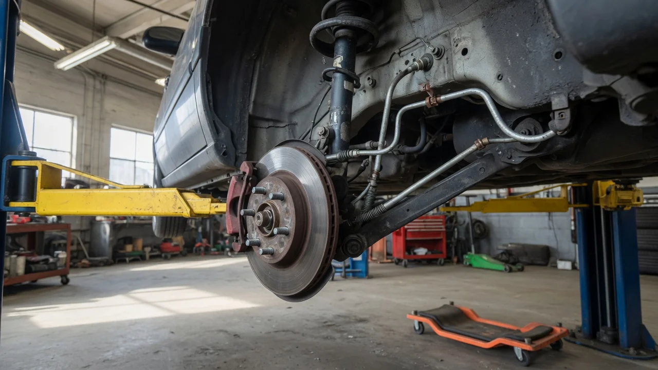
Most Escorts of this era are described as having front disc brakes and rear drum brakes. Confirm this for your specific car, because the end-point components on the diagram, and the parts you buy, depend on it.
How to trace the circuits
1) Find the master cylinder and count its outlets. Each outlet starts a separate hydraulic circuit. 2) Follow each outlet to the next component: a proportioning or control valve on non-ABS cars, or the ABS unit on equipped cars. 3) From that component, follow each line toward a wheel. Note where a rigid line meets a flexible hose, since these junctions are the usual service and replacement points. 4) Identify which wheels each circuit feeds. Many front-wheel-drive cars use a diagonal split, where one circuit feeds one front wheel and the opposite rear wheel. Others split front and rear. Use the diagram to confirm which arrangement your car has rather than assuming. 5) Note the clips, brackets and grommets the diagram marks along the underbody. Replacement lines should follow the same path so they stay clear of the exhaust, suspension and moving parts.
The split arrangement matters in practice. It determines which wheels lose braking if one circuit fails. It also affects the bleeding sequence, which is the order in which you purge air from each wheel after opening the system. Use the bleeding order in the service manual for your exact configuration. ABS cars may need extra steps or a scan tool to cycle the control unit.
What to verify before replacing lines
Line diameter and fitting type: not covered here; confirm from the service manual or by inspecting the original line. Flare style at each connection: must match the original, as mismatched flares can leak under pressure. Torque specifications for fittings and banjo bolts: use the factory figures for your vehicle. Whether replacement lines come pre-bent for your body style and ABS configuration, or must be bent to match the original routing. The condition of the flexible hoses and the parts they connect to, since lines are often replaced because of corrosion that may also affect nearby fittings.
Brake lines are safety-critical. If the diagram is unclear, or a fitting is seized or corroded, have a qualified technician inspect the system before you drive the car.