WARN Locking Hub Parts Diagram: Components, Layout and How to Use It
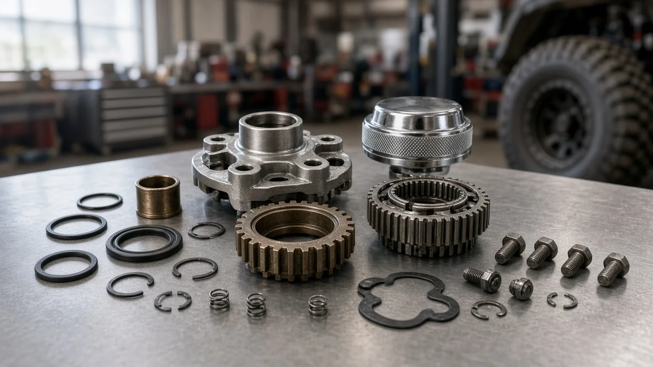
A WARN locking hub parts diagram is an exploded view of a manual hub. It shows the order in which the dial, cap, clutch parts, springs, retaining rings and seals stack together on the end of a front axle. Owners usually look for one when a hub will not lock, slips under load, leaks or has been taken apart. This guide explains what the diagram represents, what changes it from one hub to another, and how to use it during inspection and reassembly.
What a WARN hub diagram shows
Most WARN manual hub diagrams follow the same layout, read from the outside of the wheel inward. On the outside is the control dial or knob, which you turn between FREE and LOCK. Behind it are the cap or dial retainer and the small screws that hold the assembly together. Next comes the clutch mechanism: a sliding clutch gear or ring, the spring or springs that move or hold it, and the inner drive gear that fits over the axle shaft splines. The hub body, or housing, contains these parts and mounts to the vehicle's wheel hub. Retaining rings, snap rings, washers, O-rings and gaskets are shown at the points where they locate or seal each part.
The direct answer has an important limit. There is no single universal WARN hub diagram. Part shapes, the number of internal pieces, and the way the hub attaches to the vehicle depend on the specific hub model and the application it was built for. A diagram is only reliable for your hub if it matches that exact hub. Normally that means the exploded view in the installation or service instructions supplied with your hub or rebuild kit, or one tied to the part number on the hub.
How a manual locking hub engages the axle
On a part-time four-wheel-drive vehicle, the front wheels turn whether or not the front axle is driven. A locking hub controls the connection between the axle shaft and the wheel. In FREE, the clutch gear is held out of engagement. The wheel and hub body then spin on their bearings while the axle shaft, front differential and related parts stay largely still. This reduces wear and drag in two-wheel drive.
Turning the dial to LOCK lets the clutch gear move along its splines so that it bridges the inner drive gear, which is fixed to the axle shaft, and the internal splines of the hub body. Torque can then pass from the axle into the wheel. The springs shown in the diagram supply the force that moves or holds the clutch gear, and the dial typically uses a cam or ramp to control its position. Engagement depends on gear teeth lining up. For that reason, a hub that is set to LOCK may not fully engage until the wheel rotates slightly.
Why diagrams differ between hubs and vehicles
WARN has sold more than one manual hub line, such as Standard and Premium hubs, and the internal designs are not identical. Within each line, individual hubs are made for particular vehicle configurations. Axle spline count, axle shaft size, mounting stud or bolt pattern, and the way the hub body seals against the wheel hub can all vary. A diagram for one application can therefore look correct while showing a different drive gear, a different spring arrangement or a different retaining method from the parts in your hand.
Service history matters too. A previous owner may have fitted aftermarket hubs in place of factory ones, swapped axle parts, or rebuilt the hub with a kit from another series. Some vehicles came from the factory with hubs that look similar but were not made by WARN, and their exploded views will not match WARN parts. Before you rely on any diagram, confirm the hub's identity from the markings on the dial or body, your purchase records, or the documentation that came with the hub.
Using the diagram during inspection and service
The most practical use of the diagram is as a disassembly map. Photograph each layer as you remove it and lay the parts out in the same order as the exploded view. Snap rings and springs are easy to put back facing the wrong way, and a reversed part can stop the clutch gear from moving fully. Note which side of each ring or washer faces outward before you remove it. If the diagram shows a part you cannot find, stop and work out whether it was lost, was never fitted, or belongs to a different version of the hub.
While the hub is apart, compare each component with its position in the diagram and inspect it for problems that affect engagement. Look for chipped or rounded teeth on the clutch gear and drive gear, weak or broken springs, a cracked dial, and damaged or missing O-rings. Check also for water, rust or burned-looking grease inside the body. Moisture usually means a seal has failed, often at the dial or where the body meets the wheel hub, and those seals should be replaced rather than reused if they are hardened or cut. Clean old grease out of the internal parts and relubricate them with the type and amount specified in the instructions, since excess or wrong grease can affect how freely the clutch moves.
When you reassemble, follow the order in the exploded view and the tightening values in the hub or vehicle service information, not a figure from memory. With the vehicle safely supported, turn each dial through both positions and rotate the wheel by hand to confirm the hub frees and locks. Check the second hub as well, because both front hubs must be set the same way before you use four-wheel drive.
Limitations and next step
A general description like this one can explain what the parts do, but it cannot replace the diagram and specifications for your exact hub and vehicle. Some hub problems also start outside the hub. Wheel bearing play, a worn axle shaft or U-joint, or a transfer case or front axle that is not engaging can produce symptoms that look like a hub fault. If a correctly assembled hub still slips, makes noise, will not hold LOCK, or the wheel has looseness or roughness, a full front-end inspection is the sensible next step.
If you cannot identify your hub model, are missing internal parts, or find damage to the axle splines or the wheel hub mounting surface, contact WARN or a qualified four-wheel-drive technician. Have the hub markings and your vehicle details ready. Replacement kits and service intervals should come from manufacturer specifications for your hub and the maintenance schedule for your vehicle, adjusted for operating conditions such as water crossings, mud or frequent four-wheel-drive use.