Why Do Cars Use Twisted-Pair Wiring? Noise, Data Signals, and Repair
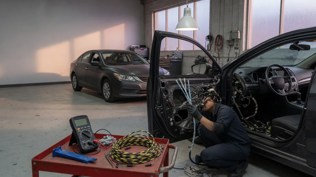
Look inside a modern wiring harness and you will often find pairs of thin wires wound around each other along their entire length. These automotive twisted pair wires carry data between control modules, and the twist is not decorative. It is a simple, inexpensive way to keep digital messages intact in an environment full of electrical noise. This article explains why cars use twisted-pair wiring, how the signals on those wires work, and what the design means when a repair is needed.
Noise Rejection: Why the Twist Matters
A vehicle is an electrically noisy place. Ignition coils, alternators, fuel injectors, relays, electric motors and pulse-width-modulated loads all switch current on and off rapidly, and hybrid and electric vehicles add high-voltage power electronics to the mix. Changing currents create changing magnetic fields, and those fields can induce unwanted voltages in nearby conductors. Electric fields can also couple into wires capacitively. A long harness run that passes close to these sources can behave like an antenna, picking up interference that has nothing to do with the data it is supposed to carry.
Twisting two conductors together attacks this problem geometrically. Because the wires stay tightly side by side, both are exposed to nearly the same interference. Each half-twist swaps their positions relative to the noise source, so the small loop formed between the wires alternates direction along the cable. Voltage induced in one loop tends to oppose the voltage induced in the next, and over many twists much of the interference cancels. The twist also keeps the loop area between the conductors small, which further limits magnetic pickup. Whatever noise remains tends to appear almost equally on both wires, which is exactly the kind of noise a differential receiver is designed to ignore.
The benefit works in both directions. When the two wires carry equal and opposite currents, their magnetic fields largely cancel, so the pair radiates less energy of its own. That helps a vehicle avoid interfering with its radio receivers and other electronics. Twisted pairs achieve this without the added cost, weight and stiffness of a fully shielded cable, although some applications still combine twisting with shielding where conditions demand it.
Data Signals: Differential Communication on a Pair
Most twisted pairs in a vehicle carry differential signals. Instead of measuring one wire's voltage against chassis ground, the receiving module looks at the voltage difference between the two wires. On a Controller Area Network (CAN), for example, the wires are called CAN High and CAN Low. In one logical state the two lines are driven apart, and in the other they settle toward the same voltage. The receiver effectively subtracts one line from the other. Noise that lands equally on both wires, known as common-mode noise, disappears in that subtraction. Differential signaling also makes communication less sensitive to small ground voltage differences between modules mounted in different parts of the vehicle.
Twisted pairs are used by several in-vehicle networks, including CAN and its faster CAN FD variant, FlexRay, and forms of automotive Ethernet designed to run over a single twisted pair. Not every network works this way. LIN, a common low-cost bus for simpler components, uses a single wire referenced to ground and relies on lower data rates to remain robust. Which networks a particular vehicle uses, and where, depends on its electrical architecture.
As data rates rise, the wiring itself starts to behave like a transmission line. A consistently twisted pair has a fairly predictable characteristic impedance, and networks such as CAN place termination resistors at the ends of the bus to match it. Proper termination absorbs the signal at the ends of the line instead of letting it reflect back and distort later bits. This is one reason the physical construction of the pair, not just its electrical continuity, affects whether a network communicates reliably.
Repair: Preserving the Pair When Fixing Damage
Network wiring can be damaged by chafing against brackets, rodent activity, corrosion at connectors, collision damage or poorly installed accessories. Symptoms often include several warning lights at once, communication-related trouble codes, modules that drop offline, or faults that come and go. Before cutting or splicing anything, consult the manufacturer's service information. Some manufacturers publish specific repair procedures, specify approved splice methods or repair kits, or restrict splicing on certain high-speed networks. Those instructions take priority over general advice.
Where splicing is permitted, the general goal is to keep the repaired section behaving like the original pair. Keep the untwisted length as short as practical and re-twist the wires through the repair. Use wire of matching gauge and suitable insulation, make solid crimped or soldered connections, and seal them against moisture. Staggering the two splices so they do not sit side by side reduces bulk and lowers the risk of the conductors shorting together. Keep the pair together, route it as it was originally routed, away from high-current wiring, and be careful never to swap the two conductors.
Basic checks can help confirm a repair. With the vehicle powered down as the service procedure directs, measuring resistance between the two lines of a CAN bus reflects the termination resistors. Many classic CAN layouts use one 120-ohm resistor at each end, which measures roughly 60 ohms across the pair, but expected values depend on the vehicle's design, so compare against the published specification. An oscilloscope can show whether signal shapes are clean, which a simple continuity test cannot reveal.
Practical implications and limits
Twisting reduces interference but does not eliminate it, and its effectiveness depends on balance between the two conductors. A corroded terminal, a partially broken strand or a long untwisted section can make one wire behave differently from the other. Once the pair is unbalanced, noise no longer cancels as well. This is why a network fault may appear only while the engine is running, a cooling fan is switching or a high-power accessory is active, and why a vehicle can pass a quick check at rest yet misbehave on the road. Some low-speed, fault-tolerant network designs can keep communicating in a degraded mode after a single-wire fault, while others cannot, so the presence or absence of symptoms does not prove the wiring is healthy.
It also helps to remember that a twist alone does not identify a wire's purpose. Some sensor circuits are twisted or shielded for similar noise reasons without being part of a data bus, so wiring diagrams are the reliable way to know what a pair carries. Tapping into network wires for aftermarket equipment can load or unbalance the bus, so a purpose-built interface is the safer route. For high-speed networks such as automotive Ethernet, or harnesses routed near high-voltage components in hybrid and electric vehicles, repair tolerances may be tighter and safety procedures stricter. In those cases, following the manufacturer's guidance or seeking professional diagnosis is the practical choice.