What Is a Sensor Reference Voltage in a Car?
A sensor reference voltage is a stable, regulated voltage that a vehicle control module sends to many of its sensors. The sensor uses that supply to produce a signal, and the module reads the signal against the same known value. On many vehicles the reference is about 5 volts, which is why technicians often talk about a five volt reference sensor circuit. This article explains how the supply is shared, how it is measured, and what goes wrong when it fails.
Shared Supply: Where the Reference Comes From
Inside the engine control module, or another module such as a transmission or body controller, a voltage regulator turns the fluctuating system voltage into a steady reference. Battery and charging voltage rise and fall as electrical loads change, so feeding sensors directly from that source would make their readings drift. A regulated reference gives every sensor on the circuit the same predictable starting point.
A typical three-wire sensor has a reference wire, a signal wire and a ground wire, often called the low reference or sensor return. Many of these sensors are ratiometric: their signal is a proportion of the reference they receive. A pedal or throttle position sensor, for example, acts like a variable divider, so its output moves between near zero and near the full reference as the part moves. Because the module knows the reference value, it can turn that proportion into a position, pressure or other measurement. Two-wire temperature sensors differ: the module feeds reference through an internal resistor, and the sensor's changing resistance moves the voltage on that wire.
To save wiring, one regulated output usually feeds several sensors through splices in the harness. Depending on the vehicle, a single reference circuit might supply sensors for throttle position, accelerator pedal position, manifold pressure, fuel tank pressure, refrigerant pressure or some camshaft and crankshaft position sensors. Many modules provide more than one reference circuit, and manufacturers often divide related sensors between them so that one fault does not disable everything at once. Which sensors share a circuit is vehicle-specific and can only be confirmed from the wiring diagram for that vehicle.
Measuring a Sensor Reference Voltage
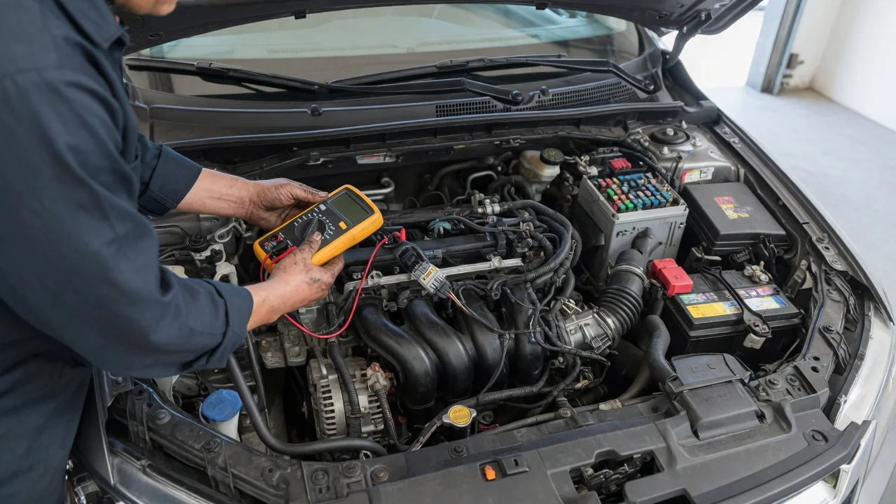
The usual tool is a digital multimeter with high input impedance, which reads the circuit without loading it. With the ignition on and the engine off, the reference is typically measured at the sensor connector by back-probing the reference terminal while the connector stays plugged in, or by using a breakout lead designed for that connector. Piercing wire insulation is best avoided, since the hole can let moisture in and create a future fault. Incandescent test lights are also a poor choice on these circuits because they draw current the reference was never designed to supply.
Where the black lead goes matters. Measuring from reference to the sensor's own ground shows the voltage the sensor actually has available to work with. Measuring from reference to the battery negative terminal shows what the module is putting out. If those two readings differ noticeably, the sensor ground path may have resistance. Comparing the reading with the connector plugged in and unplugged also helps: a reference that is correct with the sensor disconnected but sags when it is connected points toward excessive load somewhere on the circuit. The specified value and acceptable range should come from the vehicle's service information rather than a general rule.
Some scan tools display a reference voltage parameter on certain vehicles, allowing a quick check without opening connectors. For intermittent problems, an oscilloscope or graphing meter can reveal brief dropouts that an averaging meter may miss, especially while the harness is gently flexed.
Common Reference Voltage Faults
The most recognizable pattern comes from a short to ground on a shared reference circuit. When one sensor or wire pulls the reference low, every sensor on that circuit loses its supply at the same moment. The result is often a burst of trouble codes naming several unrelated sensors, along with symptoms such as reduced power mode, an illuminated warning lamp, erratic gauge readings or, if a crank or cam sensor is involved, a stall or no-start. Many modules also set a dedicated reference circuit code. Generic codes such as P0641, P0651 and P0697 describe sensor reference voltage circuits A, B and C, though the exact codes and labeling vary by manufacturer.
Other failures behave differently. A short to a higher voltage source can push the reference above its intended value and may damage sensors or module circuitry. An open in the reference wire to a single sensor affects only that sensor, which usually reads stuck at one end of its range. High resistance from corrosion, a spread terminal or a damaged splice can leave a reading that is plausible but wrong. Common causes include chafed harnesses near brackets or moving parts, water in connectors, a sensor with an internal short, and accessory wiring that has been tapped into a sensor circuit.
Because a shorted sensor can take down the whole circuit, a standard isolation approach is to monitor the reference while unplugging the sensors on that circuit one at a time. If the voltage recovers when a particular sensor is disconnected, that sensor or its branch of the harness is the likely cause. If it stays low with everything unplugged, the problem lies in the shared wiring or, less commonly, in the module's internal regulator.
Practical Implications and Limits
For owners, the most useful takeaway is that a trouble code naming a sensor does not prove the sensor itself has failed. When several codes appear together for parts that seem to have nothing in common, a shared reference or ground circuit deserves attention before any parts are replaced. Swapping a sensor that was only reporting a supply problem can cost money without changing the symptom, and replacing a control module without first ruling out the harness is an expensive way to find a chafed wire.
There are limits to what general knowledge can tell you. Reference values, the number of reference circuits, which sensors share each one, and the codes the module sets are all decided by the manufacturer and can differ between engines in the same model line. Some sensors are fed from switched system voltage rather than a regulated reference, and some newer designs send digital signals that a voltmeter cannot interpret meaningfully. A single static reading taken in the driveway also cannot rule out a fault that only appears with heat, vibration or moisture.
A careful owner with a meter and the correct wiring diagram can often confirm whether the reference is present and stable. Probing module connectors or interpreting waveforms is usually better left to a technician with factory-level service information.