What Is a Floor-Mounted Headlight Dimmer? Placement, Wiring and Restoration
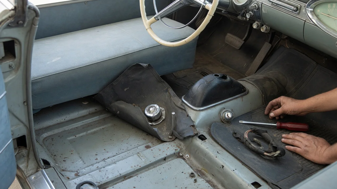
A floor-mounted headlight dimmer is a foot-operated switch, set into the driver's floorboard, that toggles a car's headlights between low and high beam. Before most manufacturers moved this function to a lever on the steering column, the classic foot dimmer switch was a familiar fixture in many older vehicles. Understanding where it sits, how it is wired and how it wears helps owners keep original lighting reliable and decide how to restore it correctly.
Switch placement
The switch is typically mounted on the floor or the lower toe board to the left of the pedals, where the driver can reach it with the left foot. A round button, or plunger, protrudes through the floor covering, while the body of the switch sits underneath it or is bolted to a small bracket. Each press of the button moves an internal mechanism that alternates between the low-beam and high-beam circuits, so the switch stays in its selected position until it is pressed again. This latching action means the driver does not need to hold the button down to keep the high beams on.
The exact location varies by vehicle. In some cars the switch sits low and far to the left near the kick panel; in others it is closer to the clutch or brake pedal. Many installations use a rubber boot, grommet or trim ring around the button to help keep debris and water out of the floor opening. Because the switch is mounted in the floor pan, it shares that area's exposure to moisture from wet shoes, leaking seals and condensation, a factor that shapes much of its service life. A factory service manual or body diagram for the specific vehicle is the reliable way to confirm the original position and mounting hardware.
Wiring
Electrically, a floor dimmer is a simple selector switch. In a common arrangement it has three connections: one input that receives power from the main headlight switch when the headlights are turned on, and two outputs, one feeding the low-beam filaments and the other feeding the high-beam filaments. The high-beam output usually also supplies the dashboard high-beam indicator. The dimmer does not turn the headlights on or off by itself; it only routes the power that the headlight switch has already sent to it.
Connections are made either through a molded plug that slides onto blade terminals or through individual terminals secured with screws or spade connectors, depending on the design and era. The wiring runs from the switch toward the dash harness, often along the floor or kick panel under the carpet. In many older systems without headlight relays, the full current drawn by the headlamps flows through the dimmer contacts and the connected wires. That makes contact condition and terminal tightness important, because added resistance at any point can produce heat, voltage drop and noticeably dimmer lamps.
Wire colors and terminal identification are not universal. Manufacturers used different color codes, and later repairs may have replaced original wiring with whatever was on hand. Before disconnecting anything, it is sensible to note or photograph which wire goes to which terminal and compare the layout with a wiring diagram for the vehicle. A test light or multimeter can confirm which terminal is the live feed with the headlights on and which outputs correspond to each beam.
Restoration
Floor dimmer problems tend to show up as symptoms the driver notices immediately: one beam setting that does not work, lights that flicker or drop out when the button is pressed, a button that feels gritty or fails to latch, or both beams lighting at once. Because similar symptoms can also come from the headlight switch, bulbs or sealed beams, poor grounds or harness damage, diagnosis should start by checking whether power reaches the dimmer input and whether it leaves through the correct output in each position. If power arrives but does not pass through reliably, the switch itself is the likely fault.
Restoration usually involves lifting the floor covering around the switch, unbolting the switch from the floor or bracket and disconnecting the wiring. Corroded external terminals can sometimes be cleaned, but the internal contacts of a sealed switch are generally not serviceable, so replacement with a correct-type switch is the common approach. While the switch is out, it is worth inspecting the plug or terminals for heat discoloration, checking wire insulation for cracking, and examining the surrounding floor metal for rust, since a wet or rusted floor can undermine both the mounting and the new switch.
When reinstalling, a solid mounting, a properly seated connector and an intact boot or grommet help keep water out. Some owners add a headlight relay so that the dimmer switches only a small control current while the relay carries the lamp load. This can reduce stress on the dimmer contacts, but it changes the original circuit, so it is a choice between originality and electrical margin. Any modification should be documented so later owners and technicians understand what was changed.
Practical implications and limits
In daily driving, a foot dimmer asks more of the left foot than a column stalk does. In vehicles with a manual transmission, the driver may need to move that foot between the clutch and the dimmer, and thick-soled shoes or an oversized floor mat can make the button harder to find or press firmly. Mats that cover or rest on the button can also cause unintended switching, so positioning or trimming them around the switch is a practical precaution. Because the button usually latches rather than acting momentarily, a quick high-beam signal means pressing it twice rather than pulling a lever.
The description in this article covers the typical design, but details such as terminal count, connector style, mounting method and whether a relay is fitted depend on the specific vehicle and sometimes on earlier modifications. Replacement switches that look similar may have different terminal layouts or mounting provisions, so matching the part to the vehicle matters. For accurate work, the vehicle's own service manual and wiring diagram remain the reference, and any lighting repair should leave the headlights properly aimed and fully functional on both beams.