What Is a Crankshaft Position Sensor Used For?
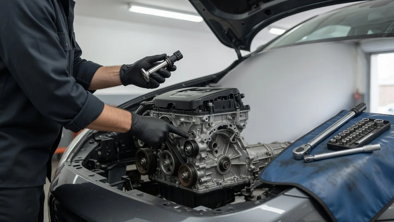
A crankshaft position sensor tells the engine computer how fast the crankshaft is turning and where it sits in its rotation. That stream of pulses underpins nearly every timing decision a modern gasoline engine makes, from when to fire each spark plug to when to open each fuel injector. If you have wondered what a crankshaft position sensor is used for, the short answer is engine control itself. Without a usable crank signal, many engines will not run at all.
Speed and position
The sensor faces a toothed target, often called a reluctor or tone wheel, that turns with the crankshaft. Depending on the engine design, the target may be part of the crankshaft itself, a ring behind the harmonic balancer, or a feature on the flywheel or flexplate. As each tooth passes the sensor tip, the sensor produces a pulse. There are two common designs. A magnetic, or variable reluctance, sensor generates its own alternating voltage, and that signal grows stronger as engine speed rises. A Hall-effect or magnetoresistive sensor is powered by the engine computer and switches its output on and off. This produces a cleaner square-wave signal that stays readable even at very low cranking speeds.
The engine computer reads speed by measuring the time between pulses, so shorter gaps mean higher rpm. Position is harder to read. A wheel of identical teeth only tells the computer that the crank is moving, not where it is. To solve that, most tone wheels include a reference mark. This is typically a gap where one or two teeth are missing, or a deliberately different tooth pattern. When the computer sees that mark, it knows the crankshaft has reached a fixed angle relative to top dead center, and from there it counts teeth to track crank angle continuously. A four-stroke engine turns the crankshaft twice per complete cycle, so the crank signal alone cannot always tell a compression stroke from an exhaust stroke. Many engines therefore pair it with a camshaft position sensor to identify which stroke each cylinder is on. The crank sensor remains the primary, high-resolution reference.
The same signal feeds several other functions. On many vehicles it drives the tachometer and supplies the engine speed used for idle control and transmission strategy. Onboard diagnostics also use it to detect misfires. When a cylinder fails to fire, the crankshaft slows very slightly during that cylinder's power stroke, and the computer can see that small change in tooth timing. On engines with variable valve timing, the computer compares the crank and camshaft signals to measure how far the camshaft has actually been advanced or retarded. That comparison ties the crank sensor directly to valvetrain control.
Spark timing
Spark timing is where the crank sensor's precision matters most. For the air-fuel mixture to produce useful work, the spark must occur at a specific crank angle before the piston reaches top dead center. That ideal angle shifts with engine speed, load, temperature and fuel quality. The engine computer selects a target advance from its calibration. It then uses the crank signal to schedule the ignition coil's charge time and firing point for each cylinder. Because the crank is always moving, the computer effectively predicts when the crankshaft will reach the target angle from the most recent tooth timing, and fires the coil at that moment.
Fuel injection depends on the same reference. In sequential port injection and direct injection, each injector pulse is timed to a particular point in the engine cycle, so the computer needs accurate crank position to know when to open each injector. Where knock control is used, the computer may retard timing for an individual cylinder after detecting knock. It needs the crank signal to apply that correction to the right cylinder at the right moment. If the crank signal becomes noisy, drops teeth or arrives with a phase error, the resulting timing can be wrong even though the rest of the system works. That can show up as hesitation, misfire or reduced power.
No-start clues
Because so much depends on this signal, a dead or disconnected crank sensor commonly causes a crank-no-start. The starter turns the engine normally, but there is no spark and often no injector pulse. A few clues point toward the crank signal rather than fuel delivery or a weak battery. On many vehicles the tachometer stays at zero while cranking if the computer receives no crank pulses. A scan tool may also show zero rpm during cranking. A stored code for the crankshaft position sensor circuit, such as P0335 or a related code, points the same way. Some engines can start using the camshaft sensor as a backup, often with a longer crank time, so this behavior is not universal.
Failures are not always total. A sensor that is starting to fail, or a damaged connector or harness, may make an engine stall suddenly and then restart after cooling down. Heat can change the behavior of an internal fault or a weak connection. Other clues include stalling without warning, intermittent loss of the tachometer reading, rough running, or misfire codes across several cylinders. These symptoms overlap with ignition, fuel and wiring faults. They are reasons to examine the crank signal, not proof that the sensor itself has failed.
Practical implications and limits
For owners, the practical value of understanding the sensor is knowing what to check before replacing parts. A fault code names a circuit or signal problem. The cause can be the sensor, its connector, the wiring between it and the computer, a damaged or contaminated tone wheel, or an incorrect air gap after other engine work. Metal debris on a magnetic sensor tip, a chafed harness near the exhaust, or a connector with corroded pins can set the same code as a failed sensor. Testing methods, acceptable signal patterns and any resistance values are specific to each design. They should come from the service information for the exact engine.
Location and access also vary widely. Some sensors are bolted to the front of the engine near the crankshaft pulley. Others sit in the engine block, in the transmission bell housing, or behind other components. Some engines require a relearn procedure with a scan tool after replacement so that misfire detection works properly. Replacement parts should match the original design, because a sensor of the wrong type or output may not be read correctly. Finally, a working crank sensor does not guarantee correct timing. A jumped timing belt or chain, worn guides, or a slipped camshaft sprocket can trigger a crank-to-cam correlation fault even when both sensors are healthy. For that reason, the crank sensor is best understood as one part of the engine's timing system rather than the whole of it.