What Is a Car's Package Drawing? Occupants, Dimensions and Constraints
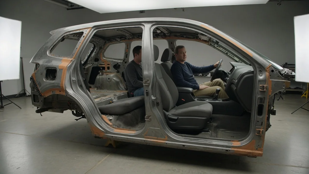
A car's package drawing is the master layout that shows where people, components and key reference points sit inside a vehicle's outer envelope. Engineers create it early in a program, before styling surfaces or detailed parts exist, to confirm that occupants, powertrain, wheels, cargo and safety space can all coexist. Understanding a vehicle packaging drawing explains why cars are shaped the way they are and why interior space always trades against other goals.
Occupants and hardware
The package drawing usually starts with people. Designers place representations of occupants, typically two-dimensional manikins or digital human models sized to cover a range of body sizes, from a small adult to a large adult. Each seating position is anchored by a seating reference point that approximates the occupant's hip joint, together with a heel point where the foot rests and defined angles for the torso, knee and ankle. From these points the layout derives the driver's eye position for visibility studies, the clearance between head and roof, and the reach to the steering wheel, pedals and controls. Rear occupants are positioned relative to the front seats so that knee room, foot space and head clearance under the sloping roof can be checked.
Hardware is added around the people. Typical items include the engine or electric motor, transmission, cooling module, exhaust system or high-voltage battery, fuel tank, steering column, crash structures, spare wheel or repair kit, and the cargo volume. Wheels and tires are shown not just at rest but as envelopes that capture their full movement through steering lock and suspension travel. Many components appear as simplified blocks or envelopes rather than finished parts, because the purpose at this stage is to reserve space and expose conflicts, not to define detailed geometry.
The layout is normally presented in side, plan and front or rear views, and today it generally lives in a three-dimensional CAD model rather than on a drafting board. The term package drawing still describes that coordinated arrangement, regardless of the software used to build it.
Key dimensions
Exterior dimensions set the outer boundary. Wheelbase, the distance between front and rear axle centers, strongly influences cabin length and ride character. Overall length, width and height define the footprint and how the car fits roads and garages. Front and rear track widths affect stability and the room left for wheel arches. Front and rear overhangs determine how much structure and crush space sits ahead of and behind the wheels. Ground clearance and, on vehicles intended for rough terrain, approach, departure and breakover angles describe what the body can clear without contact.
Interior dimensions describe the occupant space. Common measurements include front and rear legroom, headroom, shoulder room and hip room, along with the couple distance, which is the fore-aft spacing between front and rear seating reference points. Seat height above the floor, step-in height, door opening size and cargo length, width and opening height are also recorded. In North America, many of these follow standardized definitions such as those in SAE J1100, so that a given dimension is measured the same way across programs rather than by each team's own method.
A third group links the interior to the exterior. These include the cowl point at the base of the windshield, the windshield rake angle, hood height, beltline height and the upward and downward vision angles available to the driver. Small changes to any of them ripple through the package, because moving one reference point often shifts the seat, the roof, the hood and the instrument panel at the same time.
Design constraints
Regulatory and safety requirements are among the firmest limits. The package must reserve crush space in the front structure and room for side-impact protection in doors and pillars. Pedestrian protection rules in many markets call for clearance between the hood skin and hard components beneath it. Lighting and bumper mounting heights, minimum driver fields of view and mirror visibility are also regulated, and the exact rules differ from market to market. A vehicle sold in several regions must satisfy the strictest combination of these requirements in one shared layout.
Engineering constraints follow from the hardware itself. Front wheel envelopes at full steering lock limit how far forward the footwells can extend and influence the turning circle. Cooling systems need unobstructed airflow paths. Longitudinal drivelines may require a tunnel through the floor, while a battery mounted under the floor raises the floor and often the seating positions. Components must remain reachable for service, and the body must be buildable on the intended assembly line. When a new model shares an existing platform, certain hard points such as the dash panel, axle locations or floor structure may already be fixed, which narrows the available choices.
Styling and aerodynamics press from the outside. A low, sloping roofline improves appearance and can reduce drag, but it cuts rear headroom and complicates entry. A low hood looks sleek yet competes with engine height and pedestrian clearance. Wider tires and larger wheels change the wheel envelopes and intrude on the cabin. The finished package is therefore a negotiated compromise among designers, engineers, safety specialists and product planners rather than the optimum for any single goal.
Practical implications and limits
For anyone evaluating a car, the package explains many everyday impressions. How high you sit, how easily you climb in, whether a tall passenger fits behind a tall driver and how much of the road you see over the hood all trace back to decisions fixed in this layout. Published specifications such as legroom or cargo volume come from the same family of measurements, but they are only directly comparable when the figures were taken with the same procedure. Volumes and room measurements calculated under different standards or by different methods can differ even for a similar physical space.
There are also clear limits to what a package drawing can tell you. Manufacturers generally treat these layouts as internal engineering documents, so owners rarely see them directly. The manikins represent ranges of body size, not any specific person, and real comfort also depends on seat cushion compression, adjustment range, materials and posture habits that a static layout cannot capture. The drawing reflects design intent at a given stage; the production vehicle can differ after later revisions. That is why prototyping programs typically follow the package with physical seating bucks and mockups, where real people can sit in the space and confirm what the drawing predicts.
For maintenance and repair, a package drawing is not a substitute for the service manual. It shows where major components are located and how much space surrounds them, which can help explain why some jobs are difficult, but it does not provide procedures, torque values or part details. Treat it as the blueprint for how a vehicle's space was allocated, not as a guide to working on a particular car.