Transfer Case Shift Motor Connector: Identifying the Correct Connection
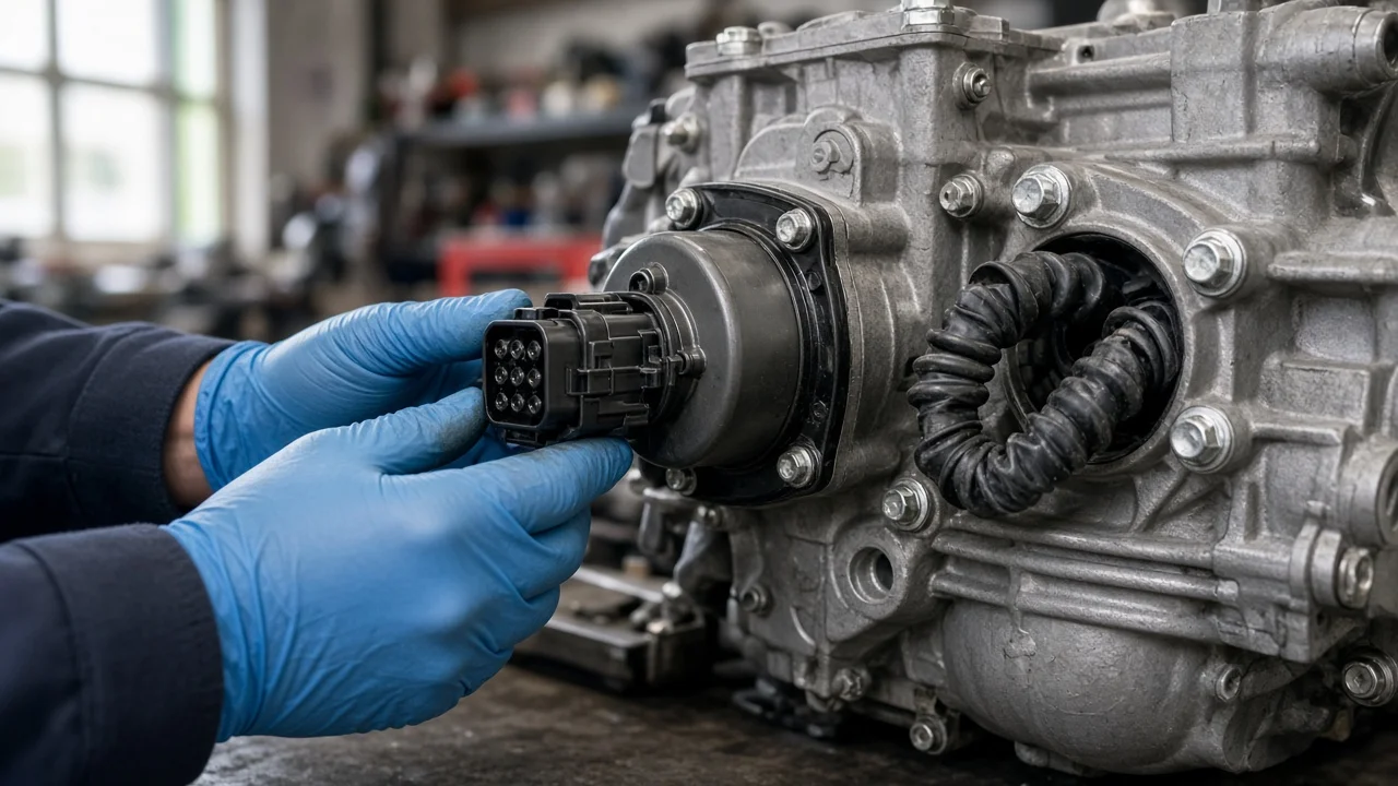
If your four-wheel-drive system won't shift, or you are replacing the transfer case shift motor, the connector is often where the trouble starts or where a repair goes wrong. The correct connection matches your exact vehicle configuration: the housing shape, keying, terminal count and circuit layout specified for your transfer case. This guide explains how to identify that plug, what affects the answer, and when to rely on vehicle-specific service information.
The short answer
The correct shift motor connector is the harness plug designed for that specific motor on that specific transfer case. It should mate with the motor without force, click fully into its lock, and match the terminal arrangement shown in the wiring diagram for your vehicle. On most electronic shift-on-the-fly systems, the plug sits on or very close to the motor, which is bolted to the outside of the transfer case. If the harness plug does not fit, has a different number of cavities, or has to be modified to seat, you almost certainly have the wrong connector or the wrong replacement motor.
No single universal connector exists for this part. Manufacturers, model years and transfer case versions differ, so identification always comes back to the exact vehicle. The best confirmation is a VIN-based parts lookup combined with the factory wiring diagram.
How the shift motor and its connector work
The shift motor, sometimes called an encoder motor or transfer case actuator, is a small electric gear motor. It rotates a shift shaft inside the transfer case to move it between ranges such as two-wheel drive, four-wheel high and four-wheel low. A control module powers the motor in one direction or the other based on the driver's selector switch. That module may be a dedicated transfer case module or a function inside another module.
The module also needs to know where the shaft actually is. For that reason, many motors contain a position sensor or encoder, and the connection carries those signal and reference circuits in addition to the heavier wires that drive the motor. Depending on the design, one connector may handle all of these circuits, or the motor and position sensor may use separate plugs. Because the module depends on that feedback, a loose, corroded or mismatched connection can cause failed shifts, flashing indicator lights, stored fault codes or a transfer case that stops between positions.
What changes the answer
The first factor is the transfer case itself. The same truck line may offer different transfer cases depending on trim, drivetrain package or model year, and those units can use different motors and plugs. Vehicles with a floor-mounted shift lever generally have no shift motor at all, while electronic shift and automatic four-wheel-drive systems do. Harness and connector designs can also change partway through a model year, which is why a VIN-based lookup is more reliable than year, make and model alone.
Operating conditions affect what you find at the plug. Trucks used off road, driven through deep water, exposed to road salt or pressure-washed underneath are more likely to show corrosion, broken locking tabs or water inside the housing. Service history matters too: an earlier repair may have left an aftermarket motor, a spliced pigtail or a replacement harness section, so the plug on your vehicle may not match original photos or diagrams.
The area around the transfer case often has other connectors nearby, such as speed sensors, a front axle actuator or position switches. Do not assume the closest plug belongs to the shift motor. Trace the wires directly from the motor to its mating connector.
How to identify the correct connection on your vehicle
Start with the part. Read the label or stamping on the existing motor and compare it with the replacement; matching part numbers, or a confirmed supersession, is the strongest evidence the plug will fit. Then compare the connector housings side by side: overall shape, keying ribs or slots, number of terminal cavities, latch style and any color coding. Photograph the original connector and harness routing before removal so the new motor can be connected and the wiring clipped back in the same path, clear of the exhaust and driveshaft.
During inspection of the harness side, look for green or white corrosion on the terminals, pushed-back or spread terminals, cracked housings, missing seals and a locking tab that no longer holds. Work only with the vehicle safely supported and the wheels secured, and follow the service procedure regarding battery disconnection. Many replacement procedures also require the transfer case and the new motor to be in matching positions before installation, so check that requirement for your vehicle before bolting the motor on.
Once installed, the connector should push on smoothly and lock with an audible or tactile click. Test each range afterward, ideally with a scan tool that can read transfer case codes and position data, to confirm the module recognizes the motor. If codes remain or the shift still fails, the problem may lie further back in the wiring, in the module, in the selector switch or inside the transfer case.
Repairing or replacing a damaged connector
If the motor is good but the harness plug is damaged, replacement pigtails are available for many applications. A pigtail is only correct if its housing and terminal layout match the original exactly, and each wire must be joined to the same circuit it replaces. Confirm that against the wiring diagram rather than relying on wire color alone. Use sealed, properly crimped splices, because this location is exposed to water, salt and heat. Twisted wires wrapped in tape tend to fail and can create intermittent faults that are hard to trace later.
Avoid cutting off a connector to make an incompatible motor fit. Reversed drive wires or misrouted sensor circuits can make the module misread the shaft position, set faults or drive the motor in the wrong direction.
Limitations and when to get professional help
This guide cannot give a pinout, wire colors or terminal count for your truck, because those depend on the exact configuration and are defined in the manufacturer specifications and wiring diagrams. Use factory service information or a reputable repair database for circuit identification, and confirm parts through a VIN-based lookup. The connector has no separate maintenance schedule interval; it is checked during routine inspection or when symptoms appear.
Get professional help if the fault returns after installing a new motor with a clean connector, if codes point to circuit or module faults you cannot isolate with a meter, if the transfer case grinds or stays locked in four-wheel drive, or if the harness has been heavily modified. A technician with a capable scan tool can command the motor and watch position feedback, which is often the fastest way to separate a connector problem from a motor, module or internal transfer case fault.