How to Replace a Transmission Speed Sensor
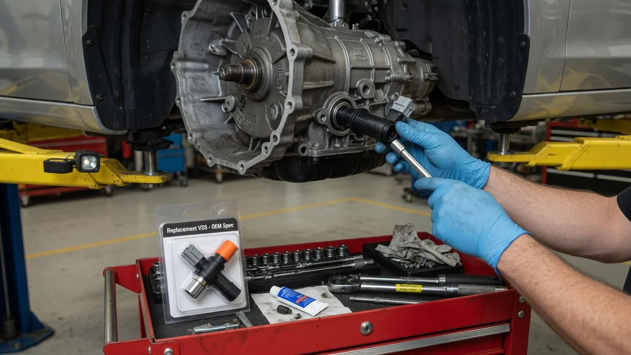
A faulty speed signal can upset shift timing, the speedometer and cruise control, which is why many owners consider transmission speed sensor replacement once a related trouble code appears. On many vehicles the job is simple: one connector, one bolt and an O-ring. On others the sensor sits inside the transmission or is built into an electronic control unit. This guide covers how to confirm you are replacing the right part, how to reach it safely, and how to check the result afterward.
Confirm the part and repair scope
Start by identifying the transmission type and exact configuration from the vehicle information label, build data or a parts lookup by VIN. Many automatic transmissions use more than one sensor. An input or turbine speed sensor reads the shaft driven by the torque converter. An output speed sensor reads the shaft that drives the wheels. Some vehicles also have a separate vehicle speed sensor on the transmission, while others use wheel speed sensor data instead. Manual transmissions usually have only an output or vehicle speed sensor. Location, connector style and fitment differ between models and even between production years, so match the replacement to the specific position and transmission, not just the vehicle name. Automatic transmission speed sensor replacement can also vary in difficulty. Some sensors bolt to the outside of the case. Others mount on the valve body or are integrated into a control module, which means draining fluid or removing the pan.
Next, make sure a sensor is actually the fault. Diagnostic codes such as P0715 (input/turbine speed sensor circuit), P0720 (output speed sensor circuit) or P0500 (vehicle speed sensor) describe a signal problem, not a confirmed failed part. The same code can come from a damaged harness, a corroded or loose connector, low or contaminated fluid, a damaged tone ring, or a control module fault. Symptoms such as an erratic speedometer, harsh or delayed shifts, or a transmission holding one gear in a fail-safe mode can have several causes. Review the service history, check fluid level and condition, and inspect the wiring. Where possible, watch live sensor data with a scan tool. If one sensor drops out or reads zero while the others report normal speed, the sensor or its circuit is a strong lead. A clean, steady signal points elsewhere. If the sensor is internal or part of a control unit, professional repair options may cost less than a mistake.
Prepare tools and safe access
Get the vehicle-specific service procedure before buying tools or parts. It should list the sensor location, fastener size, torque value, whether fluid must be drained, the correct fluid specification and any scan tool steps needed afterward. For an externally mounted sensor, you will usually need a basic socket set with extensions, a torque wrench, a trim tool for the connector lock, a drain pan, clean lint-free rags, and the replacement sensor with a new O-ring. A scan tool that reads transmission codes and live data is strongly recommended for both diagnosis and verification. Keep the correct transmission fluid on hand in case some is lost while you change the sensor.
Many sensors are reached from underneath the vehicle. Park on a level, solid surface, set the parking brake, chock the wheels, and support the vehicle on rated jack stands, never on a jack alone. Let the exhaust and transmission cool, because hot fluid and components can cause burns. Follow the service information on whether to disconnect the battery. Some jobs are better left to a shop. These include sensors that require pan removal, valve body work or a mechatronic unit, and any job where you lack proper lifting equipment.
Remove without avoidable damage
Clean the area around the sensor and connector before touching anything. Dirt that falls into the opening can end up in the transmission's hydraulic circuits. Release the connector lock carefully, because plastic tabs on older harnesses become brittle with heat. Check the terminals for corrosion, bent pins or fluid intrusion; finding damage here may change the repair. Place the drain pan underneath, since some fluid may escape when the sensor comes out, then remove the retaining bolt or bracket. Twist the sensor gently back and forth while pulling straight out. Do not pry against the sensor tip or the case, because a seized sensor can break and leave pieces in the bore. If it will not move, apply a little penetrating oil around the body and give it time rather than force. On designs that require draining fluid and dropping the pan, follow the service sequence exactly, including pan bolt order and filter handling.
Once the sensor is out, examine the tip. Many speed sensors are magnetic and naturally collect a light film of fine particles, which can be wiped away. Heavy metal chunks, large flakes or a damaged tip suggest internal wear or contact with a rotating part. Diagnose that further before closing everything up.
Install and restore the system
Compare the new sensor with the old one. The body length, tip shape, mounting flange, O-ring and connector should all match. Fit a new O-ring if one is supplied, and lightly lubricate it with the specified transmission fluid so it does not tear on insertion. Push the sensor in straight until the flange sits square against its seat. Start the bolt by hand, then tighten it to the torque in the service information. Overtightening can crack the flange or the transmission case. Reconnect the connector until it locks, and route the harness through its original clips, away from exhaust components and moving parts.
Restore the fluid level using the fluid specification for that transmission. The checking procedure varies. Some units use a dipstick. Many sealed transmissions require a check or fill plug, a specific fluid temperature and the engine running, and reading that temperature may require a scan tool. Clear stored codes after the repair. Depending on the manufacturer, a transmission adaptation reset or relearn may be needed after replacing a speed sensor. This is more likely when the sensor is part of a control module, and integrated units may also need programming. Follow the applicable instructions rather than assuming the vehicle will adapt on its own.
Check the completed work
With the engine running, check the sensor and connector for leaks, then lower the vehicle and recheck the fluid level as specified. On a road test, watch the speedometer and the cruise control, if equipped. Note the shift behavior through every gear, including downshifts while slowing. If you have a scan tool, compare the input, output and vehicle speed readings. They should rise smoothly and in proportion to each other, without dropouts or sudden spikes. After the drive, check again for pending or stored codes.
Further diagnosis is needed in four cases: the same code returns, the live reading stays at zero or remains erratic, shifting problems continue after any required relearn, or a new leak appears. Test the circuit as described in the service manual, and look for chafed or shorted wiring at the harness and connector. Confirm the tone ring is intact, and consider whether the control module or an internal mechanical fault is responsible. If a new sensor changes nothing, that is useful evidence that the original fault lay elsewhere.