Ford Manual Locking Hub Diagram: Parts, Order and How They Work
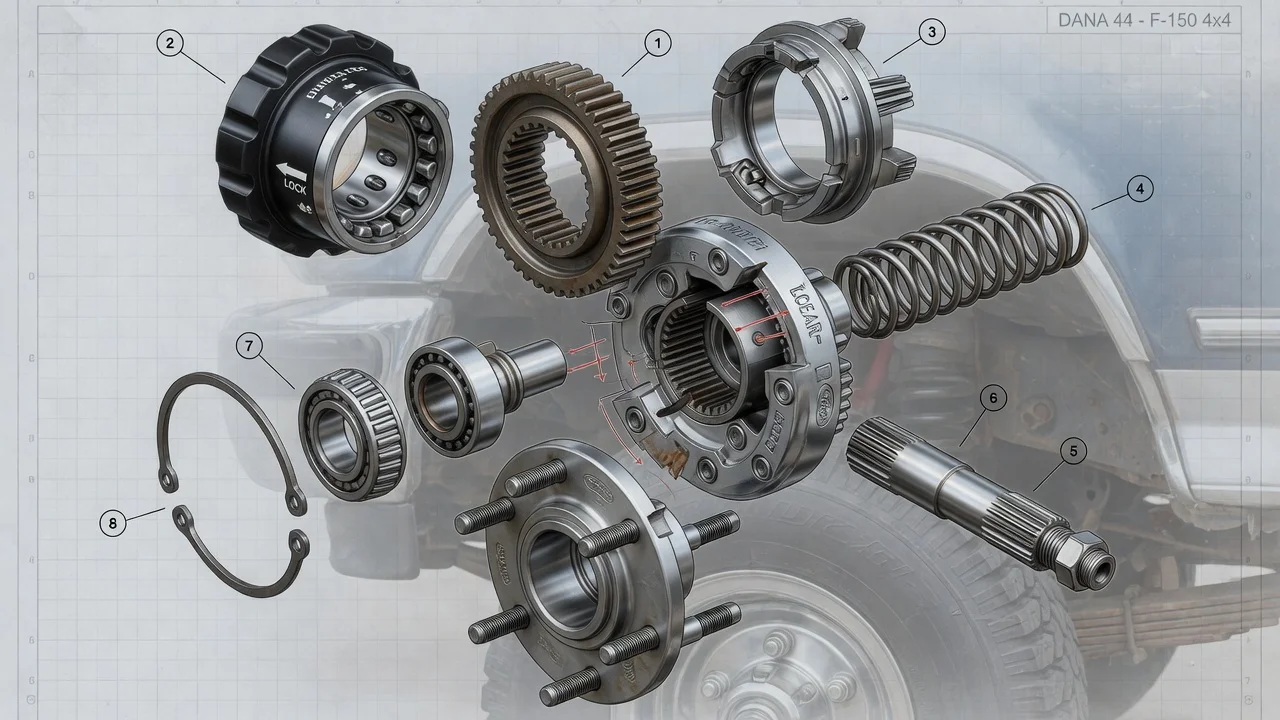
A manual locking hub diagram shows how the dial on the front wheel of a Ford four-wheel-drive truck connects or releases the front axle shaft. Owners usually look for one before taking a hub apart, rebuilding it, or chasing a hub that will not lock. This article describes the typical parts and their order. The exact diagram depends on the truck's year, front axle and hub manufacturer, so use this as a guide to reading your own service information.
What a Ford manual hub diagram shows
An exploded diagram of a Ford manual locking hub, read from the outside in, usually follows the same basic sequence. At the front is the control dial or knob, usually marked LOCK and FREE, held in a cap or housing. Behind it is a retaining ring or a set of cap screws. Next is the clutch assembly: a cam or actuating mechanism turned by the dial, one or more springs, and a sliding clutch gear with internal teeth. Then comes an inner clutch ring or drive gear that fits onto the splined end of the front axle shaft, usually held by a snap ring or retaining clip on the shaft. The hub body mounts to the wheel hub in one of two ways. It either sits inside the wheel hub on splines, held by a large internal snap ring, or bolts to the wheel hub's outer face. Behind the locking hub, and often on the same page, are the wheel bearing locknut, lock washer or keyed washer, adjusting nut, and the bearings on the spindle.
Reading the diagram this way shows that a manual hub is a removable coupling layered over the wheel bearing assembly. Keeping the hub's own parts separate from the bearing hardware behind it helps you decide how far you actually need to take things apart.
How the locking mechanism works
The front differential drives the axle shaft, while the wheel hub rotates on its bearings with the wheel. In FREE, the sliding clutch gear is held away from the gear on the axle shaft. The wheel spins without turning the shaft, the differential or the front driveshaft. Turning the dial to LOCK rotates a cam that lets spring pressure push the clutch gear inward until its teeth mesh with both the hub body and the axle shaft gear. The wheel and axle shaft then turn as one unit.
This has two practical consequences. First, the hub only locks the wheel to the axle. The front axle still gets no power until the transfer case is shifted into four-wheel drive, and both front hubs must be locked for the front axle to drive properly. Second, engagement relies on a spring, so if the teeth are sitting tooth-to-tooth they may not mesh the moment you turn the dial. Rolling the vehicle a short distance or rotating the wheel slightly normally lets them drop into place. A dial that turns but never engages points to a problem inside the clutch assembly rather than the transfer case.
What changes the diagram for your truck
Ford used more than one style of manual hub across its light trucks and SUVs, and aftermarket replacements add more variation. The main distinction is between internal and external hubs. Internal hubs fit inside the wheel hub and are held by an internal snap ring. External hubs bolt to the outside of the wheel hub with a ring of cap screws. The two look different on paper and come apart in different ways. Several other details also decide which diagram applies: front axle design, the number of axle shaft splines, whether the truck uses separate inner and outer locknuts, and whether it was built with automatic hubs instead of manual ones.
Automatic locking hubs work through a different mechanism and are serviced differently. Some later trucks also engage the front axle by vacuum or electrical control instead of locking hubs at the wheel. If your hub has an AUTO position or no dial at all, a manual hub diagram will not match it. Replacement hubs from different makers may also arrange the spring, cam and clutch ring differently from the original part. For an aftermarket hub, the instruction sheet supplied with it can be more accurate than a factory illustration.
Using the diagram during inspection and service
Start by confirming the vehicle configuration: model year, drivetrain, front axle, and whether the hubs are original. Check the markings on the hub face and any service history you have, since a previous owner may have fitted a different brand. Then match the diagram from the factory service manual or the hub maker's instructions to the part actually on the truck. Before disassembly, set the dial to FREE unless your instructions say otherwise. Lay each part out in the order it comes off, and photograph each stage. Photos are more reliable than memory, particularly for snap ring and spring orientation.
During inspection, look for rounded or chipped clutch teeth, a weak or broken spring, a cracked dial, damaged seals or O-rings, and signs of water or rust inside the hub. Hardened old grease can keep the clutch from sliding and is a common reason a hub sticks in one position. Clean the parts, check the axle shaft splines and retaining clip, and lubricate with the grease type and quantity your service information calls for. Packing a hub too full can also interfere with engagement.
You can run a simple functional check with the front wheel safely raised and supported and the transfer case in two-wheel drive. With the hub in FREE, the wheel should turn without moving the axle shaft. With the hub in LOCK, turning the wheel should also turn the axle shaft, and you can usually see movement at the front driveshaft. Repeat the check on both sides.
Wheel bearings and the parts behind the hub
Many hub repairs stop at the clutch assembly, but some diagrams continue into wheel bearing adjustment because the locking hub has to come off first. The locknut, washer and adjusting nut set bearing preload. The correct procedure and torque figures differ between Ford models and years, so do not borrow a figure from another truck or a general rule of thumb. If you disturb the bearings, follow the exact sequence in the service manual for your axle and check for play and roughness afterward. Replace damaged washers or seals rather than reinstalling them. How often to inspect and repack these parts depends on the maintenance schedule and operating conditions in the manufacturer specifications for that truck. Water crossings and heavy off-road use are common reasons to look sooner.
Limits of a generic diagram and when to get help
A general description like this cannot replace the exploded view for your exact hub. Part counts, snap ring locations and spring placement all vary. A hub reassembled with one piece reversed may feel normal at the dial yet fail to lock or release. If you cannot identify the hub type, cannot find the correct diagram, or find that the parts on the truck do not match the illustration, stop and confirm before forcing anything apart.
Get professional help if any of these apply: the hub grinds or clicks under load, the axle shaft or spindle splines are damaged, the bearings show play after adjustment, or the front axle does not drive even with both hubs locked and the transfer case engaged. These symptoms can come from the axle shaft, front differential, transfer case or bearing setup rather than the hub itself. A shop with service data for your specific vehicle can diagnose them properly.