How to Replace a Driveshaft Center Support Bearing
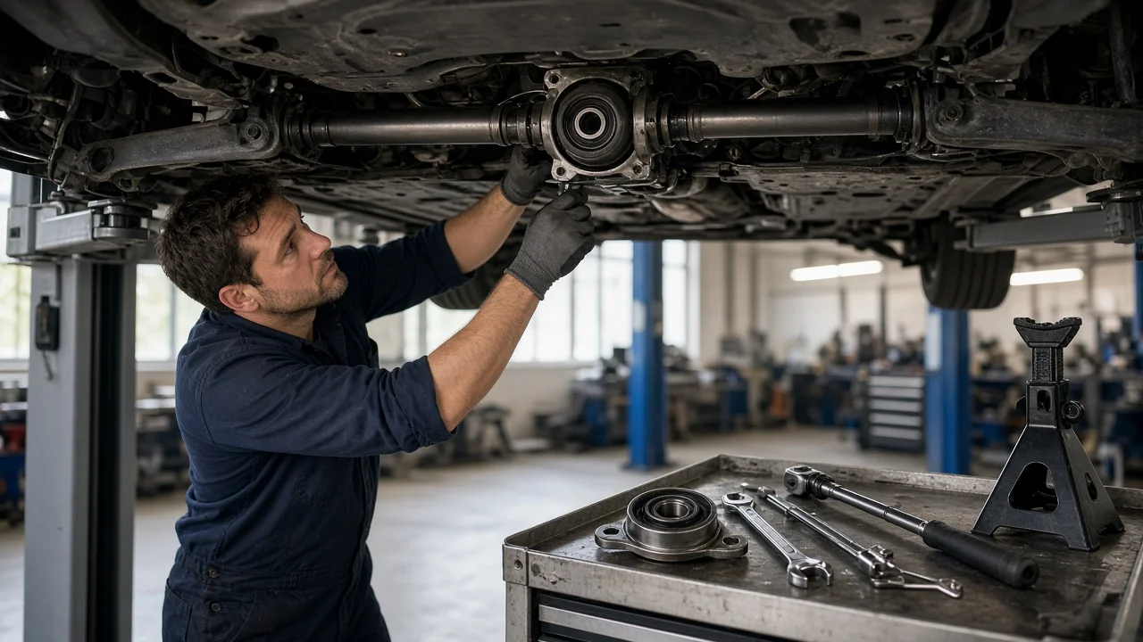
A worn center support bearing, often called a carrier bearing, lets a two-piece driveshaft sag, shake and hum. The symptoms usually get worse under load. An owner with solid jacking equipment and the right press tools can replace it, but driveshaft phasing, shim placement and fastener torque all matter. This guide covers confirming the diagnosis, removing the shaft safely, installing the new support bearing and checking the result.
Confirm the part and repair scope
A center support bearing is used only on vehicles with a two-piece or multi-piece driveshaft. These are common on longer-wheelbase trucks and vans, and on some rear-wheel-drive and all-wheel-drive cars. The part is a sealed ball bearing set in a rubber isolator, with a bracket that bolts to the chassis or a crossmember. Driveshaft diameter, spline count, bracket height and offset all vary, so match the replacement to your exact vehicle configuration. That means model year, cab and bed length or wheelbase, drivetrain, transmission and, where available, the driveshaft part number. Some manufacturers do not sell the bearing separately and supply only a complete driveshaft assembly, which changes the job entirely.
Confirm the bearing is the cause before you buy parts. Typical signs are a shudder when pulling away from a stop, a clunk on take-off or when shifting between drive and reverse, and a rumble or squeal that follows vehicle speed rather than engine speed. A visual inspection may also show a cracked, torn or separated rubber isolator. Other faults can cause similar complaints: worn universal joints, a dry slip yoke, failed transmission or engine mounts, CV joint wear on AWD shafts, out-of-balance tires, and wrong driveline angles after a lift or lowering kit. Check the U-joints for play while you are under the vehicle and review the service history for recent driveline work. If the joints are original and worn, consider replacing them now, since the shaft will already be out.
Prepare tools and safe access
Get the service information for your specific vehicle first. You need the removal procedure, torque values for the flange or strap bolts and the bearing bracket, notes on single-use fasteners, and any driveline angle requirements. Do not borrow torque figures from another model. Typical tools include: • A floor jack and quality jack stands rated for the vehicle; • Wheel chocks; • A socket set and torque wrench; • A paint marker or scribe; • A bearing puller or splitter, plus a hydraulic press or suitable bearing installer; • A drain pan and a plug for the transmission tailshaft if the slip yoke will come out; Penetrating oil helps with corroded bracket bolts.
Park on level, solid ground, chock the wheels that stay down and support the vehicle on stands at the manufacturer's lifting points. Never work under a vehicle held only by a jack. Once the driveshaft is disconnected, the park position of an automatic transmission no longer holds the axle, so rely on chocks and the parking brake. Some trucks use a driveline-mounted parking brake, which will not hold once the shaft is apart. Pressing a bearing on and off a shaft needs proper equipment. If you have no press, you can remove the driveshaft yourself and have a driveline or machine shop swap the bearing. Shafts with a rubber flex coupler, a center constant-velocity joint or known balance sensitivity are reasonable jobs to leave to a shop entirely.
Remove without avoidable damage
Mark the driveshaft before loosening anything so it goes back in the same orientation. Put alignment marks across the rear flange and the pinion flange, across the front flange and transmission output if they are bolted, and across the splined joint between the front and rear sections. The two halves must go back together in the same spline position to keep the universal joints in phase. Getting this wrong can cause vibration even with a perfect new bearing. Also note the position and number of any shims between the bearing bracket and the crossmember, and take photos.
If you need to rotate the shaft to reach fasteners, shift into neutral, then return the vehicle to its secured state. Remove the rear flange bolts or U-joint straps while supporting the shaft so it does not hang from a joint. If the U-joint bearing caps are not held by straps, tape them in place so the needles do not fall out. Support the center section and remove the bracket bolts. Then slide the front yoke out of the transmission, lower the assembly and plug the tailshaft to limit fluid loss. Do not bend CV joints or flex couplers past their range, and protect the tube from impacts that could dent it or knock off balance weights.
Move the shaft to the bench. Remove the retaining nut or clip at the center yoke if fitted, mark the yoke to the shaft splines, and separate the sections or pull the yoke. Press the old bearing off with a puller or splitter, pushing on the inner race and supporting the shaft so the tube is not crushed. Before discarding the old parts, note which way the bearing, bracket, dust shields and slingers face. Clean the bearing journal and splines, then check for scoring, corrosion or damaged splines. A worn journal can let the new bearing spin on the shaft.
Install and restore the system
Fit any new slingers or dust shields first, facing the same way as the originals. Press the new bearing onto the journal by its inner race only, until it seats against the shoulder. Pressing on the rubber isolator or outer race can damage the bearing before it ever turns. Confirm the bracket faces the direction you noted. Reinstall the yoke on its splines with your alignment marks lined up, and tighten the retaining nut or clip to the torque in the service information. Some designs need a new nut or thread locker, so follow the manufacturer specifications for your shaft.
Install the assembly in reverse order. Slide the front yoke into the transmission and line up all marks. Loosely fit the center bracket with the original shims in their original positions so the driveline angle stays as designed. Reconnect the rear flange or straps, replace any fasteners the manufacturer lists as single-use, and torque everything in the specified sequence. Some procedures require the center bracket to be tightened at normal ride height, or with the shaft centered in the bracket slots, so check that before final tightening. Top off transmission fluid if any was lost, and grease serviceable U-joints and the slip yoke where the design allows.
Check the completed work
Before lowering the vehicle, check the following: • The shaft turns freely by hand in neutral, with no binding. • It does not touch the exhaust, fuel lines or heat shields. • The bracket sits flat. • Every fastener has been torqued. • The tailshaft seal is not leaking. With the vehicle back on the ground, road test it under several operating conditions. Try gentle and firm launches from a stop, steady cruising speeds, light deceleration and a few shifts between drive and reverse. A correctly installed support bearing should run quietly and remove the take-off shudder that pointed to it.
If vibration remains, go back to diagnosis rather than replacing more parts. Vibration on launch can point to driveline angles, missing or misplaced shims, or a worn U-joint. Vibration that rises with speed may come from shaft balance, phasing or tires. A new clunk can mean a loose fastener or too much slip yoke play. Recheck the fasteners after the first drive if the service information calls for it, and include the center bearing in routine underbody inspections. There is no universal replacement interval, so follow your maintenance schedule and inspect sooner if you tow, carry heavy loads or drive off-road.