Dorman ABS Wheel Speed Sensor Wiring Harness: Fitment and Part 970-040
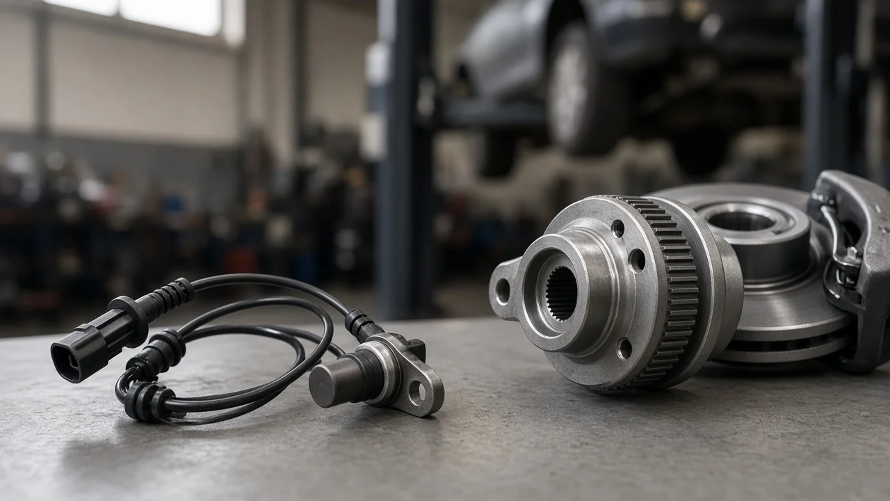
Dorman sells ABS wheel speed sensor wire harnesses to replace the short harness that carries the sensor signal from a wheel to the vehicle's main wiring. Part 970-040 is one item in that line. Whether it suits your vehicle depends on an exact catalog match, not on appearance. This guide explains what the harness does, what decides fitment, how to confirm the fault before buying, and how to install it safely on conventional and hybrid vehicles.
Does Dorman 970-040 fit your vehicle?
Fitment for the Dorman 970-040 harness has to be confirmed against your specific year, make, model, drivetrain and wheel position. This article does not list its application range, because a harness that fits one corner or trim level can be wrong for another. Use the parts catalog lookup with your full vehicle details or VIN. Then compare the replacement with the original harness: connector shape and terminal count at both ends, overall length, and the number and position of clips, brackets and grommets. If any of these differ, stop and recheck the part number before installing anything.
Buy the harness only after confirming that the wiring is the faulty part, not the sensor, the tone ring or the ABS module. Many ABS warning lights are blamed on wiring when the real cause is a contaminated sensor tip or a cracked reluctor ring. The reverse is just as common: a new sensor is installed and the light returns because a wire inside the old harness is broken.
How the wheel speed sensor circuit works
Each wheel speed sensor reads a toothed ring or magnetic encoder that turns with the hub or axle. Older passive sensors are magnetic pickups that generate their own AC voltage, which rises in amplitude and frequency as the wheel spins faster. Most newer vehicles use active sensors. The ABS module supplies them with power over one wire, and the sensor returns a digital pulse signal whose frequency tracks wheel speed. In both designs the harness is usually a two-wire circuit between the sensor and the module, although the exact pin layout must come from the wiring diagram for your vehicle.
The harness lives in a harsh place. It flexes with every suspension movement and steering input. It is also exposed to water, road salt and brake heat. Typical failures are conductors broken inside intact-looking insulation near flex points, corroded terminals that add resistance, and chafed insulation that shorts a wire to ground or to the other conductor. The ABS module checks whether each signal is plausible. When it sees an open circuit, a short, an erratic signal or no signal at all, it stores a code and usually disables ABS. It often disables traction and stability control as well.
What changes the answer
Vehicle design matters before part numbers do. On some vehicles the harness is permanently attached to the sensor, so the only correct replacement is a complete sensor assembly. On others, a separate harness section links the sensor to the body harness. Front and rear corners use different harnesses, left and right sides are often mirror images, and all-wheel-drive versions can route wiring differently from two-wheel-drive versions of the same model. Sensor type also changes the testing method: a passive sensor is checked for resistance and AC output, while an active sensor is checked for supply voltage and signal pulses.
Hybrid and electric vehicles add a second distinction. The ABS module and the wheel speed sensor circuits run on the low-voltage system, fed by the 12-volt starter or auxiliary battery. The high-voltage traction system is completely separate, and its cables are normally orange. Replacing a wheel speed sensor harness does not require opening the high-voltage system. However, do not disturb orange cables or high-voltage components near the work area. If the job requires access near them, follow the manufacturer's high-voltage disable procedure or leave the work to a trained technician.
Low system voltage can also mimic a wiring fault. A weak 12-volt battery, loose battery terminals or poor alternator or DC-DC converter charging output can make the ABS module set voltage-related codes. Confirm that battery voltage and charging are normal before condemning any wiring.
Diagnosing the circuit before you buy
Start with a scan tool that can read ABS codes and live data. The stored code usually identifies the wheel position and the type of fault. Next, drive slowly or spin the wheel and watch live wheel speeds: a wheel that reads zero or drops out while the others agree points to that corner. With the vehicle safely supported, perform a wiggle test. Flex the harness at the clips, grommets and connectors while watching live data, since a signal that cuts in and out as you move the wire strongly suggests a broken conductor or a bad terminal.
Then inspect and measure. Look for stretched, chafed or melted insulation and green corrosion in the connectors. Using the wiring diagram, unplug both ends and check each wire for continuity end to end. Also check each wire for a short to ground and for a short to the other conductor. On active sensors, check for the specified supply voltage at the sensor connector with the ignition on. Check the ABS fuses as well, and if one has blown, replace it only with the same fuse rating and look for the short that caused the failure. Fitting a larger fuse can let damaged wiring overheat.
Installing the replacement safely
Park on level ground, apply the parking brake, support the vehicle on jack stands rather than the jack, and remove the wheel if needed for access. Turn the ignition off and keep the key or smart key away from the vehicle. Disconnecting the negative 12-volt battery terminal is a sensible precaution while you unplug connectors at the module side. Be aware that this may reset radio presets or learned settings. On hybrids, use the 12-volt auxiliary battery, which can sit in the trunk or under a seat, and never treat the high-voltage pack as the battery to disconnect.
Route the new harness exactly along the original path and use every clip, bracket and grommet. Before final tightening, turn the steering from lock to lock and check the suspension at full droop. The harness must not stretch, rub a tire or brake rotor, or touch the exhaust. Make sure each connector clicks fully home and its seals are seated. Reconnect the battery, clear the codes, and road test. Confirm that the ABS warning light stays off and that all four wheel speeds match closely in live data.
Limitations and next step
This guide cannot confirm that part 970-040 fits a particular vehicle. Only a catalog match using your full vehicle details can do that, along with a side-by-side comparison with the original part. Test values, pin assignments and supply voltages vary by manufacturer, so use the factory wiring diagram and specifications rather than general figures. If codes return after a new harness, look next at the sensor, the tone ring or encoder, wheel bearing play and the ABS module connector.
Seek professional help for intermittent faults you cannot reproduce, for any work near high-voltage components on a hybrid or electric vehicle, or if the brake pedal feel or stopping behavior changes. ABS, traction and stability control are safety systems, so do not drive with a known fault longer than necessary.