Diagnose engine intake manifold temperature sensor
The short answer
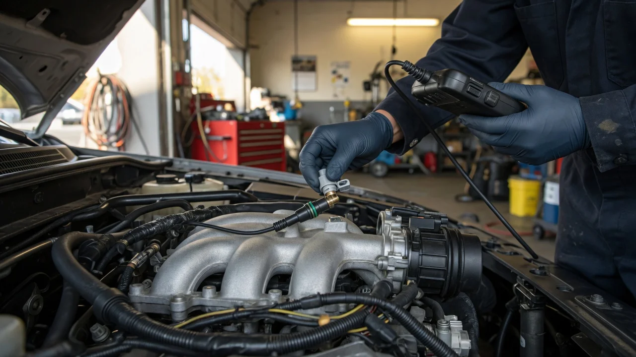
An intake manifold temperature sensor reports the temperature of the air entering the engine so the engine control module (ECM) can calculate air density and adjust fuel delivery and ignition timing. To diagnose it, do not start by replacing the part. First confirm what the scan tool reports, compare that reading with known temperatures, and then inspect the connector and wiring. A fault code tells you where to look, not which part has failed. Wiring, connectors, intake leaks and, less often, the control module can all set the same code.
Manufacturers use different names and layouts, and this changes how you test. The sensor may be called a manifold air temperature (MAT) sensor or an intake air temperature (IAT) sensor. It may be a standalone part screwed into the manifold, built into the mass airflow sensor housing, or combined with the manifold absolute pressure sensor in one unit, often called a TMAP sensor. Some engines have more than one intake air temperature sensor, for example before and after a turbocharger intercooler. Check the service information for your exact model year, engine and market to confirm which sensor the code or symptom refers to and where it is.
How the sensor works, briefly
Most of these sensors are thermistors, which are resistors whose resistance changes with temperature. The usual type is negative temperature coefficient (NTC): resistance falls as the air gets warmer. The ECM sends a regulated reference voltage through the sensor and reads the resulting signal voltage. On this common design, cold air produces a higher signal voltage and warm air produces a lower one. Exact resistance and voltage values differ by manufacturer and sensor, and no specification table was supplied for this guide, so take test values from the service manual for your vehicle rather than from generic charts.
Symptoms that can point to this sensor
A faulty or misreported intake temperature can cause the problems below. Each one has other possible causes, so treat them as reasons to investigate, not as a diagnosis.
Check engine light with an intake air temperature circuit code; Hard starting, especially when the engine is cold or after a hot soak; Rough or unstable idle; Hesitation or poor throttle response; Higher than usual fuel consumption or a rich-running smell; Spark knock (pinging) under load, if the ECM believes the air is cooler than it really is; An emissions test failure linked to fuel trim problems
Fault codes to know
Generic OBD-II codes for the intake air temperature circuit are in the P0110 to P0114 range: P0110 is a general circuit malfunction, P0111 is a range or performance problem, P0112 is a low input signal, P0113 is a high input signal, and P0114 is an intermittent signal. Many vehicles use P0095 to P0099 for a second intake air temperature sensor. Manufacturers may also define their own codes or apply these differently, so confirm the definition for your vehicle. Low input usually means the circuit is reporting a very hot reading, which can come from a short to ground. High input usually means the circuit is reporting a very cold reading, which can come from an open circuit or disconnected sensor. That interpretation depends on the circuit design, so confirm it in the service information.
What to check next, in order
1) Record the freeze-frame data and all stored codes before clearing anything. Note whether other sensor codes are present, such as MAP, MAF or coolant temperature codes, because a shared reference voltage or ground fault can trigger several codes at once. 2) Do a cold-soak comparison. After the vehicle has sat long enough for the engine to reach ambient temperature, usually overnight, turn the ignition on and compare the intake temperature reading with the coolant temperature reading and the outside air temperature. On a fully cold engine these should be close to each other. 3) Watch the reading while the engine runs. It should change smoothly and plausibly as the engine warms and as driving conditions change. It should not jump, drop out or stay stuck at one value. 4) Look at the reading for clues about the circuit. A value stuck at the scale's extreme cold end often points to an open circuit. A value stuck at the extreme hot end often points to a short. A reading that looks plausible but is wrong points more toward a sensor out of calibration or an installation problem. 5) Inspect the connector and harness. Look for corrosion, bent or pushed-back terminals, a broken locking tab, oil contamination and chafed wiring near hot or moving parts. With the engine idling, gently move the harness and watch the live reading for dropouts. 6) Check the sensor tip. Oil, carbon or dirt on the sensing element can slow its response, particularly on engines with heavy crankcase ventilation flow into the intake. 7) Test the circuit with a multimeter using the manufacturer's procedure. That procedure normally covers sensor resistance at a known temperature, reference voltage and ground integrity at the connector. Compare your results with the published specification for your vehicle. 8) Rule out related problems. Intake leaks, a sensor fitted in the wrong location, or a missing heat shield can make a working sensor report unusual temperatures.
Interpreting the results
Observation | What it most likely indicates | Next step; Reading stuck at extreme cold value | Open circuit, unplugged sensor or failed-open sensor | Check connector seating and wire continuity, then sensor resistance; Reading stuck at extreme hot value | Signal shorted to ground or failed-shorted sensor | Inspect harness for chafing and test for short to ground; Cold-soak reading far from coolant and ambient values | Sensor out of calibration, contaminated element or added circuit resistance | Clean or inspect the sensor and check terminals for corrosion; Reading drops out when harness is moved | Intermittent connection | Repair terminals or wiring before replacing the sensor; Several sensor codes set together | Shared reference voltage or ground problem | Diagnose the common circuit before replacing any single sensor; Sensor and wiring test within specification but the code returns | Possible control module or software issue | Check for manufacturer service bulletins or software updates and seek professional diagnosis
When to stop driving or get professional help
An intake temperature fault on its own is rarely an emergency. Many ECMs switch to a default value and the engine keeps running, often with reduced performance or higher fuel use. Stop driving and arrange a tow or inspection if the check engine light is flashing, which usually signals active misfiring that can damage the catalytic converter. Do the same if you hear sustained heavy knocking under load, the engine stalls in traffic, you smell fuel, or the temperature gauge shows overheating. Get professional diagnosis if the wiring problem is inside a hard-to-reach harness, if several sensor circuits fail together, if all tests pass but the fault keeps returning, or if your vehicle needs dealer-level software or calibration tools.
Gaps to keep in mind
This guide covers the general principles of intake temperature sensing and OBD-II diagnosis. It does not include vehicle-specific resistance tables, voltage specifications, sensor locations, torque values or the exact code definitions for any particular make, model year or engine. Those details decide whether a measured value is in or out of specification, so get them from the service manual or a qualified technician for your vehicle before replacing parts.