Catalytic Converter Sensors: Identifying the Sensor and Its Function
Before you start
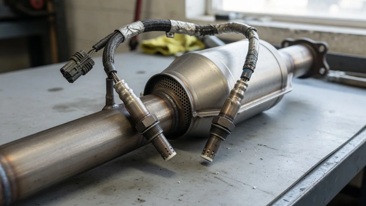
A catalytic converter does not contain one type of sensor. The term catalytic converter sensor usually refers to the oxygen sensors mounted in the exhaust path around the converter. Most modern gasoline vehicles have an upstream oxygen sensor before the catalytic converter and a downstream oxygen sensor after it. The upstream sensor helps the engine control module adjust the air-fuel mixture. The downstream sensor mainly monitors how well the converter is cleaning the exhaust. On a diesel vehicle, the converter-related sensor names may differ and the setup may include exhaust temperature or pressure sensors.
Checking these sensors is a local procedure on the vehicle. No account, app or online service is required. You will need enough access to the exhaust area, but you do not need to disconnect the battery for a basic visual inspection. If you replace a sensor, follow the exact procedures for your vehicle model because connector design and removal tools vary.
Step-by-step instructions
Find the sensor locations
Let a hot exhaust cool before you reach near the converter. Start by identifying the catalytic converter under the vehicle. The upstream oxygen sensor is located in the exhaust pipe before the converter, often close to the engine. The downstream oxygen sensor is located after the converter. On an inline engine there is frequently one sensor before and one after the converter. A V-type engine may have a sensor for each cylinder bank, giving two upstream and two downstream units in some configurations.
Check the visible wiring and connectors
Follow each sensor body to its wiring connector. Look for a burned or melted wire sleeve, a loose connector, green corrosion on the pins or a damaged cable that could rub against the exhaust or body. Do not pull on the wire. A cracked sensor body, damaged heat shield or obvious exhaust leak near the sensor can affect its readings.
Read the fault codes
Use an OBD-II scan tool or code reader to check diagnostic trouble codes. Codes that mention an oxygen sensor heater circuit, sensor response, circuit voltage or bank and sensor position help identify which unit is involved. The sensor position is usually shown as sensor 1 for upstream or sensor 2 for downstream. Bank 1 and bank 2 describe the sides of a V-type engine. A code naming a range or performance problem may point to the converter rather than the sensor itself.
View live data carefully
If the scan tool supports live data, look at the oxygen sensor voltage or equivalence ratio. The upstream sensor normally changes faster as the engine control module makes corrections. The downstream sensor should be more steady once the converter is warm and working. Treat exact voltage ranges as vehicle-specific. Do not assume a specific reading means the sensor or converter is faulty without comparing it to the manufacturer values for that model.
Remove only the sensor you can identify
Disconnect the connector before unscrewing the sensor if you need to remove it. Use the correct oxygen sensor socket to reduce the chance of rounding the hex. Mark the old sensor location so the new part goes back into the same position. Some sensors use anti-seize on the threads from the factory; do not apply extra compound to every new sensor because the requirement depends on the part design.
Check the output
After inspection or replacement, make sure the wiring is routed without touching hot parts. Clear old fault codes only if the tool permits it and you have noted them first. Run the engine until it reaches normal temperature, then check that the new or reconnected sensor does not set a fresh code. A short test drive may be needed for some monitor-based checks, but the actual readiness procedure depends on the vehicle manufacturer.
The on-board diagnostic result is a practical verification, not proof of a flawless exhaust system. It shows whether the sensor circuit responds within the expected limits. It does not confirm exhaust flow, converter internal condition or every type of wiring fault.
Common problems and next steps
Wrong sensor selected
A common mistake is buying a part based only on the phrase catalytic converter sensor. Confirm the sensor position, bank, heater type, connector shape and thread size. A part may look similar but have a different connector or operating range. Use the vehicle identification number and the exact engine variant when checking parts compatibility.
Sensor and converter codes overlap
The downstream sensor can report a converter efficiency problem even when the sensor itself is functioning. Diagnose the sensor heater, wiring and response first. Then check for exhaust leaks, misfire conditions or contamination that would prevent the converter from working correctly. Replacing the sensor alone may not clear a converter fault code.
Sensor threads or connector damaged
If the old sensor is difficult to remove, stop rather than forcing it with an open-end wrench. A damaged thread in the exhaust or converter can complicate repair. Use penetrating products only where the manufacturer permits and keep them away from the sensor tip and connector.
Model-specific differences
Older vehicles may have a single oxygen sensor. Newer vehicles may use wideband or air-fuel ratio sensor terminology, especially for the upstream unit. Diesel exhaust systems may use nitrogen oxide, exhaust pressure or temperature sensors around the catalyst or filter. Treat the sensor names as a clue to the location and measured value, not as interchangeable part terms.