Brake Pads and Rotors Replacement: What the Job Involves
What this job is
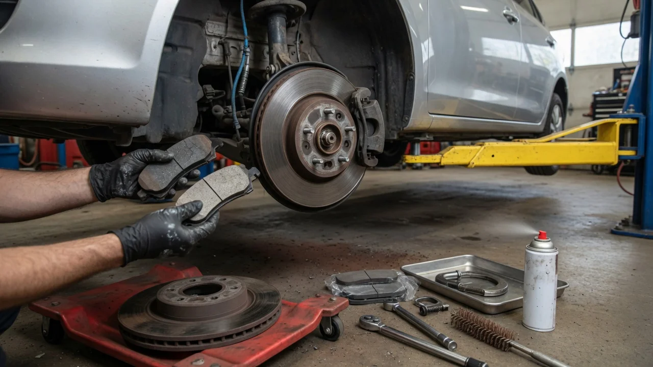
Replacing brake pads and rotors is an axle-set service: new friction material (pads) and a fresh, true braking surface (rotors) on both wheels of the same axle. The job restores stopping performance that has fallen off through wear, heat, rust or scoring. It is usually done as a pair on the front axle, the rear axle, or both, because mixing a new pad-and-rotor stack on one side with a worn stack on the other can pull the vehicle under braking.
The scope changes with the vehicle. Many cars and light trucks use a sliding-caliper disc at each corner. Some rears combine a disc with an integral parking-brake drum, an electric parking brake (EPB) caliper, or a separate drum-in-hat. Those designs add service-mode steps, special tools or extra hardware. Torque figures, minimum rotor thickness, pad wear limits, fastener reuse rules and brake-fluid type are model-specific. Those values were not supplied here and must be taken from the vehicle’s service information before any fastener is tightened or any rotor is judged thick enough to reuse.
How pads and rotors stop the vehicle
In a hydraulic disc brake, pedal force raises fluid pressure in the caliper. The caliper squeezes the pads against both faces of the rotor, which is bolted to the hub and turns with the wheel. Friction converts the vehicle’s kinetic energy into heat. Pads are sacrificial; their friction material wears down over repeated stops. The rotor also wears, can warp or develop thickness variation, and can rust or groove where the pad no longer covers the full face.
A thin, glazed or grooved rotor leaves the new pads with a poor mating surface, so shops commonly replace rotors with the pads rather than machining the old discs. Machining remains an option only when the rotor is otherwise sound and will stay above the minimum thickness stamped on the hat or rim after the cut. That minimum, and whether the manufacturer even allows resurfacing, is a factory specification, not a universal number.
What the job typically involves
The sequence below is the usual path on a conventional hydraulic sliding-caliper disc. It is an outline, not a substitute for the procedure, fastener map and torque table in the service manual for the exact year, model and brake package. Electronic parking brakes, dual-piston or fixed calipers, captured rotors behind the hub, and seized hardware all change the order and the tools.
Prerequisites and tools
Service information for that vehicle: pad and rotor part numbers, minimum rotor thickness, caliper-bracket and wheel-lug torque, piston-retract method, and EPB service mode if fitted. Matching pads, rotors and hardware for both sides of the axle; replace wear clips, abutment springs and, where specified, pad shims as a set. A lift or rated jack and stands, wheel chocks, and the correct lug-nut socket. Caliper-bolt and bracket-bolt sockets, a C-clamp or dedicated piston tool, and an EPB retract tool or scan-tool routine when the rear caliper is motor-driven. Brake cleaner, high-temperature brake lubricant only where the manufacturer calls for it (abutment tabs and slide pins, never on friction faces), and a torque wrench. Brake fluid of the specified DOT grade if a hose is opened or a piston is pushed back on a low-fluid, contaminated or aged system. Opening the hydraulic circuit requires bleeding; that step is not automatic on a pad-and-rotor swap that leaves the hoses attached.
Ordered steps
Confirm the complaint and inspect all four corners: pad thickness, rotor condition, leaks, seized slides, damaged hoses and parking-brake function. Decide per axle whether rotors will be replaced or, if allowed, machined above minimum thickness. If the vehicle has an electric parking brake, put the calipers in service mode with the specified scan tool or pedal/switch sequence before unbolting anything. Do not force a motor-driven piston. Chock the wheels that will stay on the ground, lift and support the vehicle, and remove both wheels on the axle being serviced. Unbolt the caliper. Hang it from the suspension with a wire or hook so the hose is not stretched. Do not let it dangle by the hose. Remove the pads and note inboard versus outboard, wear-sensor location and any anti-rattle hardware. Unbolt the caliper bracket if the rotor cannot come off with the bracket in place. Mark or photograph slide-pin orientation. Remove the rotor. If it is rust-bound to the hub, use the threaded jack holes in the hat where provided; avoid prying on the hat in a way that cocks the rotor against the studs. Clean the hub face so the new rotor sits flat. A rusty or dirty hub is a common cause of thickness variation and pedal pulsation after the job. Fit the new rotor. If the manufacturer specifies hub-to-rotor screws or a rust-inhibiting compound on the hat, follow that instruction. Retract the caliper piston square to the bore, watching the master-cylinder reservoir so it does not overflow. On phenolic or hollow pistons use the correct tool so the face is not cracked or cocked. Twist-to-retract pistors on some rear calipers must be turned, not only pushed. Install new abutment clips and lubricate only the contact points the manufacturer lists. Fit the new pads in the correct inner/outer positions, routing any wear sensor. Refit the bracket and caliper with new bolts if the manual says they are torque-to-yield or thread-locked one-time parts. Tighten to the specified torque in the specified sequence. Wrong caliper-bolt torque is a safety defect, not a NVH issue. Refit the wheel and tighten the lug nuts in a star pattern to the specified dry or lubricated torque, as the manual states. Lower the vehicle before the final lug pass if that is the specified method. Repeat on the other side of the same axle before road testing. Pump the pedal until it is firm, with the reservoir cap off or on per the manual, and check fluid level. A pedal that stays long or sinks points to air, a leak or a piston that was not fully seated—do not drive in that state. Carry out the pad manufacturer’s bedding procedure, typically a series of moderate decelerations from moderate speed with cooling intervals, unless the pad set is a no-bed or scorched-in design with its own instructions. Avoid a hard panic stop on cold, unbedded pads. Clear EPB service mode, verify the parking brake holds, and scan for brake or ABS faults if a tool was connected.
Precautions and where a shop should take over
Brake work is a safety-critical repair. Stop and use professional service if a caliper piston will not retract, a slide pin is frozen in the bracket, a hose is cracked or wet, the rotor is captured behind a hub that must be pressed off, an EPB motor will not enter service mode, the pedal stays soft after pumping, or a warning lamp remains on. Seized hardware on salt-belt vehicles can snap caliper bolts or damage aluminum knuckles; that is a shop job with heat, extraction and possible fastener replacement, not a pad-kit afternoon.
Do not reuse crushed copper washers on banjo bolts if a hose is disturbed. Do not mix pad compounds across an axle. Do not apply grease to the pad face or rotor ring. Brake dust from older linings may contain hazardous fibres; wet-clean rather than blowing the caliper with compressed air.
Completion check
Pedal is firm within a few pumps and stays firm under a moderate hold at a stop. No grind, clunk or metal-on-metal on the first rolling metres; a light new-pad transfer smell during bedding can occur, a hot burning smell with smoke should not. Steering stays straight under a moderate stop in a safe, empty area; a pull suggests a seized slide, a contaminated pad or a hose problem that the pad swap did not fix. Lug nuts and caliper fasteners are at specified torque; wheels are free of trapped cleaner or grease on the rotor face. Fluid is at the marked level with the specified DOT grade, the cap is sealed, and EPB or ABS lamps are off. Parking brake holds on a grade appropriate to the vehicle’s design.
If the pedal pulsates after the job, the usual suspects are a rotor that was installed on a dirty hub, a hub with runout already out of spec, or uneven lug torque. Those causes are diagnosed with a dial indicator on the installed rotor, not by immediately replacing the new discs again. Runout limits and the allowed stacked-tolerance correction (indexing the rotor on the hub) are in the service information.
What this guide cannot specify
No vehicle identification, factory torque table, minimum rotor thickness, pad wear limit, fluid specification or bedding cycle was supplied for a named model. Treat every numeric setting in a real job as coming from that vehicle’s current service data. Aftermarket pad and rotor kits can also carry their own bedding and break-in notes; those override generic advice when they conflict.