Brake Line Replacement: What the Procedure Involves
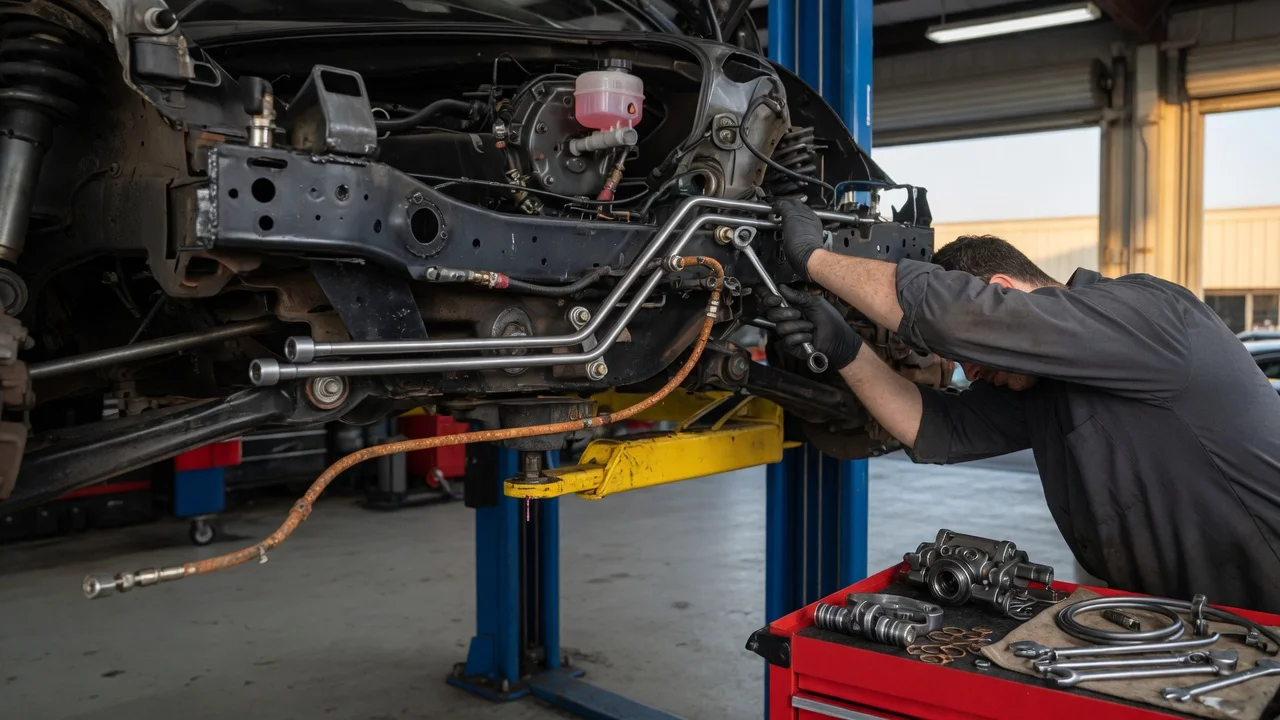
What the job actually is
Brake line replacement is the removal of a leaking, corroded, crushed, or otherwise unserviceable hydraulic pipe or hose and the installation of a new line that restores a sealed path for brake fluid from the master cylinder to the wheel brakes. The work is a safety-critical hydraulic repair, not a simple tubing swap: the new line must match the vehicle’s fitting and flare type, follow the designed route and clip points, and leave the system full of the specified fluid with air removed.
Scope changes the procedure. A short rigid-pipe section between two unions is a different job from a full chassis run, a flexible hose at a caliper, or a line that screws into an ABS (anti-lock braking system) modulator. Vehicles with electronic stability control, an electronic parking brake, or a scan-tool-only bleed sequence add steps that a basic line wrench and gravity bleed cannot cover. Always treat manufacturer service information for the specific model year, brake layout and market as the source for flare type, fluid grade, bleed order and tightening values; those details are vehicle-specific and are not interchangeable.
How the lines work, and why they are replaced rather than patched
A hydraulic brake system turns pedal force into fluid pressure at the master cylinder. Rigid metal brake pipes, often called hard lines, carry that pressure along the body, frame or subframe. Short flexible hoses bridge joints that move with the suspension or steering. At each wheel, pressure acts on a caliper piston or a drum-brake wheel cylinder so the friction material can slow the vehicle. Most modern cars and light trucks use a dual-circuit layout, so a leak in one circuit still leaves the other circuit able to apply some braking, usually with a longer pedal and reduced effect.
A compromised line lets pressure escape, restricts flow, or fails at a fitting. Visible rust-through, wet unions, a crushed pipe, a cracked or swollen hose, or internal collapse after impact all interrupt that pressure path. Clamping, sleeving or soldering a brake pipe is not an accepted repair because the joint must hold high pressure, resist vibration and corrosion, and remain serviceable at the flare seat. Damaged rigid pipe is replaced in a formed section or as a complete pre-bent run. A flexible hose is replaced as a complete assembly.
What you need before any line comes off
Confirm the vehicle’s brake-fluid specification from the master-cylinder cap and the owner’s or service literature. Glycol-based fluids (commonly labelled DOT 3, DOT 4 or DOT 5.1) are not interchangeable with silicone DOT 5. Use only the grade the manufacturer specifies, from a sealed container, because brake fluid absorbs moisture from air and that moisture lowers boiling point and promotes internal corrosion.
Identify the flare and thread before ordering or fabricating a line. Many North American applications use an inverted (SAE) double flare; many European applications use an ISO/DIN bubble flare. The wrong flare will appear to thread on and then leak or crack under pressure. Match pipe diameter, fitting threads and the original routing, including any abrasion sleeves and retaining clips. Common replacement pipe materials are coated steel, as used in many original installations, and nickel-copper (often sold as CuNi or Kunifer), which is easier to bend and more corrosion-resistant. Stainless assemblies are also used; they still require the correct flare form and fittings.
Typical tools include a quality flare-nut (line) wrench set, a tubing cutter, a bender matched to the pipe diameter, a flaring tool that can produce the exact flare the vehicle uses, a catch pan, shop rags that will be discarded, a brake-fluid-safe bleeder or a second person to stroke the pedal, jack and stands or a lift, and replacement clips and crush washers or sealing washers where the design uses them. A scan tool capable of running the manufacturer’s ABS bleed routine is required on some vehicles after the modulator has taken in air. An electronic parking brake often needs a service mode or scan-tool retract before a rear caliper hose can be removed safely.
Professional-service boundaries
Have the work done by a qualified shop when a fitting is seized in an ABS modulator, proportioning valve or aluminium housing that can strip; when the bleed procedure requires a scan tool; when an electronic parking brake will not retract with the published method; or when adjacent fuel, battery-cable or airbag components make heat or heavy force unsafe. A line that has leaked until the master cylinder ran dry can introduce air and debris into valves and the booster circuit; that condition often needs more than a hose swap. Corroded underbody pipes that crumble when a wrench is applied can turn a planned section replacement into a longer chassis run, which is a reason many owners start the job in a shop rather than mid-repair on stands.
Replacement sequence
The following order is the usual workshop sequence. Settings, fluid type, bleed order and tightening values must be taken from the applicable manufacturer procedure for that vehicle; they are not given here because they vary by model, year, brake package and market.
Park on a level surface, chock wheels that will stay on the ground, and support the vehicle on stands or a lift at the published lift points. Allow the system to cool. Protect painted surfaces; spilled glycol fluid damages paint. Record warning-lamp status and, if a scan tool will be used later, note any stored brake or ABS codes as items to investigate, not as proof that a particular line has failed. If the vehicle has an electronic parking brake, place the calipers in the published service position before disconnecting a rear hose. Disconnect the 12-volt battery only if the service information requires it for that step. Locate the damaged run. Photograph or sketch clip positions, abrasion guards and the path around fuel and brake components so the new line can be routed the same way. Place a catch pan under every union you will open. Clean dirt from fittings before loosening so debris does not enter the pipe. Use a flare-nut wrench and, on a stubborn union, a second wrench to hold the mating fitting so the pipe does not twist. Open the system at the unions that isolate the section being replaced. Cap or plug open ports on the master cylinder, ABS unit and remaining lines to limit fluid loss and contamination. Do not use taper plugs that can damage flare seats. Unclip the old pipe or unbolt the hose. Cut corroded rigid pipe only where a new union will be formed, and only with a tubing cutter that leaves a square, unsquashed end. Deburr the inside of a cut end so loose metal does not travel downstream. Form the replacement rigid line to the original bends before it is fully tightened in the vehicle, using a proper bender rather than collapsing the tube over a sharp edge. Keep the pipe away from exhaust heat, moving suspension parts, sharp chassis edges and the fuel line’s chafe points. Flare each end with the tool and die that match the vehicle’s flare type, or install a pre-bent, pre-flared line made for that application. Inspect each flare for even thickness, a smooth seat and no cracks. Replace any fitting whose threads or cone are damaged. Start every fitting by hand to confirm thread match. Route the line, refit every clip and guard, then tighten unions to the manufacturer’s value with a flare-nut wrench. A hose must not be twisted; the painted or stamped alignment marks, where present, should sit as they did on the original. Refill the master-cylinder reservoir with the specified fluid and keep it from running dry during bleeding. Bleed in the published wheel order. Dual-circuit and ABS systems often require a specific sequence; some ABS modulators need a scan-tool cycle so valves open and trapped air can leave. Continue until each bleeder discharges a stream free of bubbles and the pedal height and firmness are consistent. Torque bleeder screws as specified, refit dust caps, set reservoir level to the marked range, and fit the cap. Dispose of used fluid as hazardous waste; do not reuse fluid that has been bled out.
Completion checks
Before the vehicle carries any speed, wipe every disturbed union and hose end dry, then inspect them again after a firm pedal hold. Any wetness at a flare, hose crimp or bleeder means the joint is not sealed; do not drive until that joint is corrected. The pedal should be firm, with a stable height over several slow applications, and the brake warning lamp and ABS lamp should follow the manufacturer’s normal key-on behaviour. Fluid level should remain at the marked range.
Static leak check: dry fittings, no drip at unions, hoses or the master-cylinder body after a held pedal. Pedal check: firm, repeatable travel with the engine in the published condition for that test (running or not, as specified). Lamp check: no unexpected brake or ABS warning after a key cycle; stored codes from the repair still need diagnosis if they remain. Low-speed function check in a clear area only after the static leak check passes: straight, even response with no pull that was not present before, and no odour of fluid. Short recheck after the first drive cycle: some slow seepage appears only after heat and vibration. Recheck level and the disturbed fittings.
Precautions that belong at specific steps
Never reuse a crushed flare, a rounded fitting or a hose with damaged crimps. Tighten only to the published value; over-tightening cracks flares and strips aluminium ports. Do not use petroleum oil, ordinary grease or the wrong fluid on seals and hoses. Use only brake-fluid-compatible lubricant where a procedure calls for it. Keep open lines and the reservoir covered. Dirt in an ABS modulator is difficult to flush and can damage valves. Do not apply open flame to free a brake fitting near fuel, plastic lines or undercoating. Heat-damaged hose and pipe must be replaced. A spongy pedal after bleeding means air remains, a hose is collapsing internally, or a flare is seeping. Resolve that on the stands. A sinking pedal under a held load points to an external leak or a master-cylinder bypass; both require diagnosis before road use. If a union at the ABS unit, master cylinder or a valve block rounds, seizes or weeps from the housing itself, stop and use professional repair. Continuing can destroy a modulator that is far costlier than the line.
What this guide cannot specify without the vehicle’s service information is the exact flare standard, pipe diameter, fluid grade, union tightening values, bleed order, electronic-parking-brake retract method and whether an ABS scan-tool bleed is required. Those items change the parts you order and the last steps of the job. With the correct line, flare, fluid and bleed method, the completion standard is the same: a dry, correctly routed system and a firm, consistent pedal before the vehicle returns to the road.