What Is a Car's Diagnostic Network? Scan Tools, Modules and Limits
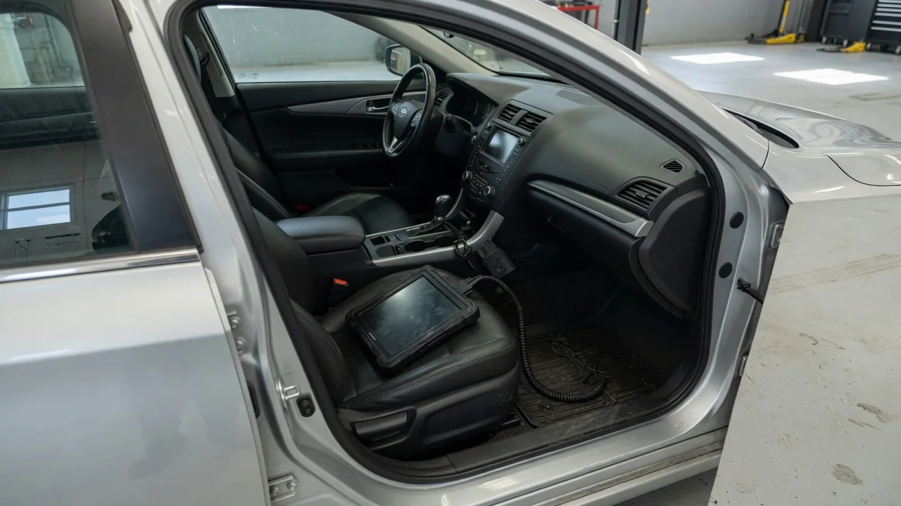
A car's diagnostic network is the set of wired data connections that lets electronic control modules share information with each other and with an outside scan tool. A reader plugged into the dashboard port joins an OBD vehicle communication network built first for the car's own operation and second for inspection. Knowing how that link works, which modules sit on it, and where its reach ends explains what a scan can and cannot reveal.
Scan Tool Link: How an Outside Device Joins the Network
The connection point is the standardized 16-pin diagnostic connector defined by SAE J1962. It is required on cars and light trucks sold in the United States from the 1996 model year onward and is normally under the dashboard, within reach of the driver's seat. Some pins supply battery power and ground so a scan tool can power itself. Others carry data, and which ones are active depends on the vehicle's communication protocol. Earlier OBD-II vehicles used one of several protocols, including SAE J1850 variants, ISO 9141-2 and ISO 14230, often called KWP2000. From the 2008 model year, US regulations require Controller Area Network (CAN) communication for OBD-II, as defined for diagnostics in ISO 15765-4.
Once connected, the tool works by request and response. It sends a message either to one module or to all emissions-related modules, and the relevant module replies. The generic services in SAE J1979 let any compliant tool read stored and pending trouble codes, live sensor values called parameter IDs, freeze-frame data captured when a fault was set, readiness monitor status and the vehicle identification number. They also let it clear emissions codes. Beyond this common set, manufacturers implement enhanced diagnostic services, often based on Unified Diagnostic Services (ISO 14229). These can reach more modules and functions, but only with a tool that knows the manufacturer's addresses, data definitions and procedures.
On many vehicles the port is not wired directly to every network. A gateway module sits between the connector and the internal buses and forwards diagnostic requests and replies. Some newer vehicles add a security gateway that allows data to be read but restricts clearing, writing or configuration until the tool is authenticated. Whether a gateway exists and how it behaves is vehicle-specific.
Control Modules: The Nodes on the Network
A control module is a small computer. It takes inputs from sensors and switches, drives actuators, and has one or more network interfaces. Common examples include the engine or powertrain control module, transmission control module, anti-lock brake module, airbag or supplemental restraint module, body control module, instrument cluster and climate control module. The list, the names and the division of work vary widely between manufacturers and model years, so one vehicle may combine tasks that another spreads across several modules.
Modules exchange data constantly during normal driving, not only during diagnosis. For example, wheel speed measured by the brake module may also be used by the transmission and the instrument cluster. To manage traffic and cost, many vehicles run several networks at different speeds. A high-speed CAN bus may serve powertrain and chassis functions, a slower bus may handle body and comfort functions, and simple LIN sub-networks may connect a master module to switches, motors or sensors. Some newer designs add FlexRay, media networks or automotive Ethernet, and some support diagnostics over IP under ISO 13400. Each module monitors the network as well as its own circuits. If expected messages from another module stop arriving, it can store a network communication code, usually shown with a U prefix.
Each module also keeps its own fault memory. A full-system scan can therefore return codes from several modules after one event, such as low battery voltage. The module that reports a fault is not always the one that failed.
Limits: What the Diagnostic Network Can and Cannot Report
Generic OBD-II was created for emissions monitoring. A basic reader that speaks only the standard services typically sees powertrain-related modules and emissions data, not airbag, brake, body or comfort systems. Enhanced access depends on the tool's coverage for the specific make, model and year, and on any gateway authentication. A tool that cannot communicate with a module does not prove that module has no faults.
A trouble code records that a module detected a condition outside its expected range under specific test conditions. It points to a circuit, signal or system behavior, not to a confirmed failed part. A sensor code can come from wiring, a connector, a mechanical problem the sensor is correctly reporting, or the module itself. Live data has limits too. Values are what the module reports or calculates, some are inferred rather than measured directly, and the diagnostic link may update them less often than the module processes them internally.
The network itself can be the fault. A shorted bus wire, a damaged connector, a failed termination resistor or a module that disrupts traffic can block communication with many modules at once, sometimes including the scan tool. In those cases the diagnostic link cannot fully describe its own failure. Physical checks with a meter or oscilloscope, following the manufacturer's procedures, are needed.
Practical Implications and Limits for Owners
For an owner, the most useful step is matching the tool to the question. A generic reader is often adequate for a check engine light, readiness status before an emissions inspection, or basic live data. Warning lights for brakes, airbags or other systems usually call for a tool with enhanced coverage for that vehicle. It is worth confirming the tool maker's stated coverage for the exact vehicle before relying on it.
Clearing codes deserves caution. Clearing emissions codes also resets readiness monitors, which can cause an inspection rejection until the vehicle completes the required drive conditions. It also erases freeze-frame data a technician might need, so record codes and freeze-frame values first. Functions that write data, such as module coding, programming or calibration, can change how the vehicle operates. They are best done only with the correct procedure, a stable power supply and a tool designed for the task.
Devices left in the port, such as insurance or telematics dongles and wireless adapters, stay connected to the vehicle's power and data lines. Depending on the device and vehicle, they may draw current while parked or interfere with other tools, so unplugging them during diagnosis is reasonable. For connector location, network layout, supported functions and test procedures on a particular car, the vehicle's service information remains the authority.