What Is a CAN Bus in a Car? Shared Messages, Wiring and Fault Clues
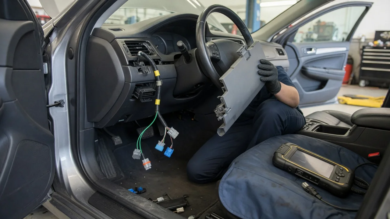
A CAN bus in a car is the shared data network that lets electronic control modules talk to each other over a small set of wires, so every signal does not need its own dedicated wire. CAN stands for Controller Area Network. This explanation covers how modules share messages, how the wiring is laid out, and which symptoms point toward a network problem rather than a single failed part. Exact layouts differ between vehicles, so treat the details here as general principles.
Shared messages: how modules talk to each other
Modern vehicles contain many control modules, such as engine, transmission, antilock brakes, airbags, body control and the instrument cluster, depending on equipment. A sensor reading is not wired separately to every module that needs it. Instead, the module that owns a piece of information broadcasts it as a message on the bus. Any other module connected to that network can read the message and use it. Wheel speed is a common example. Braking, stability control, the speedometer and sometimes the transmission may all need it. On a CAN bus, that value can be sent once and read by many receivers.
CAN messages are not addressed to a specific recipient. Each message carries an identifier that describes what the data is, and that identifier also sets its priority. Two modules may try to transmit at the same moment. When that happens, the bus resolves the conflict bit by bit. The message with the higher-priority identifier continues, and the other module backs off and retries. No data is lost, and time-critical messages tend to get through first.
The protocol also includes built-in integrity checks. Each frame contains a checksum, receiving nodes acknowledge correctly received frames, and modules keep internal error counters. A module that repeatedly detects or causes errors can limit its own participation or disconnect itself from the bus. This keeps one faulty node from silencing the rest. CAN itself does not decide what happens when data is missing or invalid. Each manufacturer's software decides, and the response may be a warning, a default value or a disabled feature.
Wiring: how the network is built
A typical high-speed CAN bus uses two wires, usually called CAN High and CAN Low, twisted together along their length. The signal is differential. Modules read the voltage difference between the two wires, not each wire's level relative to ground. Twisting the pair and reading the difference helps the network reject electrical noise from ignition, motors and other sources in the vehicle. Wire colors and routing are vehicle-specific, so you need a wiring diagram for the exact vehicle to identify them.
Electrically, the bus is a line with modules tapped onto it. In common high-speed CAN designs, each end of the line has a termination resistor, often 120 ohms, which reduces signal reflections. With both terminations in place and the power off, the resistance between CAN High and CAN Low is typically about 60 ohms, because the two resistors act in parallel. Depending on the design, termination may be built into modules or into the harness.
Most vehicles use more than one CAN bus. Many have several networks running at different speeds, for example one for powertrain and chassis and another for body or comfort functions. Other network types may handle simple devices. Gateway modules pass selected messages between networks. The diagnostic connector under the dash gives scan tools access to one or more of these networks. On vehicles that use CAN for standardized OBD-II diagnostics, the CAN pair is normally on pins 6 and 14 of that connector.
Fault clues: signs of a CAN bus problem
Because many modules depend on shared data, a network fault often produces symptoms that look unrelated. Several warning lights may come on at once. Gauges may drop to zero or behave erratically. Features such as cruise control or stability control may stop working. In some vehicles the engine may crank but not start, or not crank at all. If a problem comes and goes with bumps, temperature changes or rain, suspect a wiring or connector issue before a failed module.
Diagnostic trouble codes offer the clearest clue. Codes beginning with U are network communication codes. A message such as lost communication with a particular module suggests that module is not being heard on the bus. If many modules report lost communication with the same module, check that module first, along with its power, ground and connector. If a scan tool cannot communicate with any module on a network, the bus wiring itself may be at fault. Possible causes include a shorted wire, a failed termination or a module pulling the bus down.
Common underlying causes include low or unstable battery voltage, corroded or loose connectors, water intrusion, chafed harnesses, damage from a previous collision or repair, and aftermarket devices spliced into the network. One basic check is to disconnect the battery and measure resistance between CAN High and CAN Low at the diagnostic connector. A reading near 60 ohms is consistent with both terminations present. A much higher value can indicate an open circuit or missing termination, and a very low value can indicate a short. These readings narrow the search, but they do not identify the faulty component on their own.
Practical implications and limits
For owners, the main implication is that a single electrical problem can show up in many places. Replacing the module behind the first warning light often does not solve it, and swapping parts without network diagnosis can add cost without fixing anything. Keep the battery and charging system healthy. Modules may log communication codes when supply voltage drops during cranking or after the battery runs low.
Be careful with add-on equipment. Remote starters, trackers, performance tuners and some lighting or audio upgrades connect to vehicle networks, and a poor splice or incompatible device can disrupt communication. Probing CAN wires with a test light or piercing their insulation can also create faults. Many newer vehicles add security gateways that limit what external tools can read or command, so a generic code reader may see only part of the network.
General knowledge only goes so far. Each manufacturer defines its own network layouts, termination locations, message content and module behavior, and these can change between model years and trim levels. Interpreting U codes, locating connectors and knowing whether a replacement module needs programming all depend on factory service information for the specific vehicle. Knowing how a CAN bus works helps you describe symptoms accurately and ask better questions. Confirming a diagnosis usually still requires that service information and a capable scan tool.