Inspecting Brake Rotors Before Resurfacing: Thickness and Condition Checks
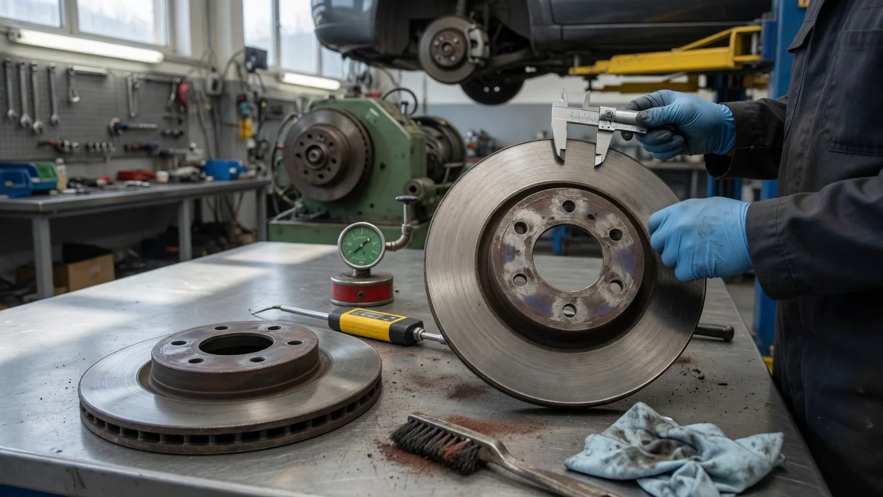
The essential check before you machine a rotor
A brake rotor should be inspected for remaining thickness and for structural or thermal damage before it is resurfaced. Resurfacing (also called machining or turning) removes metal to restore a flat, smooth friction surface. That only makes sense if the rotor will still meet the vehicle maker’s thickness limits after the cut, and if the disc is free of cracks, severe heat damage and other defects that machining cannot safely correct. Thickness limits, venting style, coating and one-piece versus two-piece construction vary by model year, generation, powertrain, trim and market, so the discard and machine-to figures on that specific rotor, or in that vehicle’s service information, govern the decision.
What you are deciding
Inspection answers two questions: whether the rotor has enough material left to machine and still remain above the published limit, and whether its condition is sound enough for continued service. If either answer is no, replacement is the supported next action. If both answers are yes, resurfacing can restore parallelism and surface finish so new pads bed in evenly. This guide covers on-vehicle and off-vehicle visual and dimensional checks of the friction rings. It does not substitute for a model-specific procedure, torque specification or thickness table, which were not supplied here and must come from the rotor stamping or the applicable service data.
Read the thickness limits on the rotor
Most passenger-car and light-truck rotors carry a stamped or cast marking on the hat, edge or inner face. Typical markings identify a minimum thickness, a discard thickness, or both. Minimum thickness is the smallest dimension the friction ring may have after machining and still remain in service. Discard thickness is the point at which the rotor must be replaced and not machined. Some rotors show only one figure; treat that as the limit you must not go below. If the marking is missing, illegible or does not match the vehicle, use the thickness published for that exact rotor part in the service information. Do not borrow a number from a similar-looking disc, another trim or another market.
Measure with a micrometer made for brake discs, not with a ruler or caliper that only spans the outer edge. Take readings at several points around the circumference and on both inboard and outboard faces, including the deepest groove. Record the smallest reading. Compare that measurement with the stamped or published limit, then subtract the amount of metal the lathe will remove to clean up both faces. If the predicted finished thickness would fall at or below the limit, do not resurface; replace the rotor. Specific millimetre or inch values are vehicle-dependent and are not listed here.
Condition checks machining cannot fix
Thickness is necessary but not sufficient. Inspect the entire friction surface, the cooling vanes or solid core, the hat and the mounting face with the wheel off and, when needed, the rotor removed. The following defects are grounds to replace rather than machine, even if thickness remains.
Cracks that extend through the friction ring, across a cooling vane, or from the hat into the disc. Hairline heat checks on the surface can be a grey area; through-cracks and cracks that reach an edge are not. Hard spots or bluish, discoloured patches from overheating. These areas are locally harder than the surrounding iron and often reappear as judder after a cut. Severe scoring, ridges or rust grooves deeper than a light machine cut can remove while staying above the thickness limit. A missing, cracked or heavily corroded hat, or elongated wheel-stud holes, which affect how the rotor sits on the hub. On composite or two-piece rotors, loose, shifted or cracked friction rings relative to the aluminium hat, and damaged fasteners between hat and ring. On coated or “coated hat” rotors, coating loss on the friction face is expected with use; coating loss that leaves the mounting face rusty and proud can cause runout and should be cleaned or the rotor replaced per the maker’s method.
Runout, thickness variation and parallelism
Lateral runout is the side-to-side wobble of the disc as it rotates. Disc thickness variation (DTV) is the difference between the thickest and thinnest points around the ring. Either can cause pedal pulsation. Service information for the vehicle sets the allowable runout and DTV; those limits were not supplied for a specific model and must be looked up. Measure runout with a dial indicator on the friction surface, typically with the rotor clamped by the wheel nuts or a suitable fixture so the hat sits as it does in service. If runout is high, first check the hub face for rust, debris or damage and the wheel-bearing play. Hub-mounted rust or a bent hub will print through to a new or newly cut rotor.
A brake lathe corrects parallelism and surface finish on a rotor that is otherwise sound and thick enough. It does not straighten a bent hat, restore a cracked ring or erase a hard spot that sits below the finished surface. If runout remains after a clean hub and a within-limit rotor, the hub or bearing is the next inspection point.
On-vehicle clues before you pull the disc
A visual pass with the wheel removed still catches many reject conditions. Look for a lip at the outer edge, which is leftover unused iron and a rough sign of wear, then confirm with a micrometer. Check for pad material transfer, glazing and rust scale on the unused inner or outer band. Inspect the caliper, slides and pads at the same time: a sticking piston or slide can taper-wear one face and make a rotor look “too grooved” on one side only. Uneven inner-versus-outer wear is a condition of the clamp hardware as much as of the disc. Replace or service the hardware that caused the taper; machining a tapered rotor without fixing the caliper repeats the wear.
When resurfacing is appropriate
Resurfacing is appropriate when the rotor is free of cracks and severe heat damage, the hub and hat mounting faces are clean and true, and the finished thickness after an even cut on both faces will remain above the published minimum or discard limit. Both rotors on an axle are commonly refinished or replaced together so left-to-right thickness and thermal mass stay similar. Match the surface finish to the pad maker’s recommendation; an overly coarse or overly polished face can delay bedding. After machining, clean the faces of swarf and anti-rust film so the new pads contact iron, not contamination.
When to replace instead
Replace the rotor if measured thickness, or thickness after the required cut, is at or below the marked or published limit; if cracks, hard spots, a damaged hat or a separated composite ring are present; or if the rotor is a non-serviceable design the maker specifies as replace-only. Many late-model coated, two-piece or very thin ventilated discs have little or no machine allowance by design. In those cases inspection still matters: you are confirming whether the disc can stay, not whether it can be cut. Always replace in axle pairs when one side is under limit or damaged, unless the service information for that vehicle says otherwise.
Next action
Find the thickness marking on the rotor or the figure in that vehicle’s service data, measure the thinnest point with a disc micrometer, inspect for cracks and heat damage, and check hub cleanliness and runout. If the disc will remain above the limit after a clean-up cut and shows no structural or thermal reject conditions, resurfacing is a supported choice. If it will not, or if those defects are present, replace the rotor and service the caliper hardware that contributed to the wear. Model-year, powertrain and market-specific limits and runout values must be taken from the applicable data; they are not universal and are not quoted here.