How to Test an Allison Transmission Output Speed Sensor
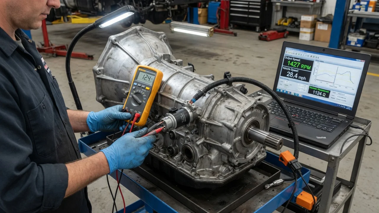
The output speed sensor reports how fast the transmission output shaft turns. The transmission control module uses that signal for shift timing and torque converter clutch control, and on many trucks it also drives the speedometer. A resistance test is useful, but it is only one step. Before you pick up a meter, identify your Allison transmission model, its control module generation and the sensor type. The specification and the tests that make sense all depend on that configuration.
Establish the symptoms
Start by writing down exactly when the problem appears. Note whether it happens cold or fully warm, at a steady highway speed or pulling away from a stop, over rough pavement, or after rain or a pressure wash. Record any signs that come with it: a speedometer that drops to zero or jumps, harsh or mistimed shifts, a transmission that holds one gear, a lit warning lamp, or cruise control that cancels by itself. Also list recent changes, such as sensor replacement, a fluid service, driveline or exhaust work near the tailhousing, a change in tire size, or new module programming.
Next, read the diagnostic codes with a scan tool that can communicate with the transmission module, not just the engine module. Note whether each code is current, pending or history, and save the freeze-frame data if it is available. An output speed code tells you the module saw a missing, erratic or implausible signal. It does not tell you which component caused it. Gather the service history as well, including when the fluid was last changed and which fluid specification was used, because that context helps separate sensor faults from other transmission problems.
Distinguish plausible causes
A failed sensor coil is the cause most people assume. The evidence supports it when the signal is lost at every speed and temperature, the code returns right after clearing, and the sensor resistance is open, shorted or outside its specification. Wiring and connector faults are just as common. They are more likely when the fault comes and goes with bumps, temperature or moisture, when the connector shows corrosion, oil intrusion or a loose lock, or when the harness rubs a bracket or sits near the exhaust. A sensor that measures within specification on the bench points you back toward the circuit.
Some causes have nothing to do with the electrical parts. Metallic debris on a magnetic sensor tip, a damaged or loose tone wheel, an incorrect air gap or an unseated sensor can all weaken or distort the signal. The wrong replacement sensor can produce a signal that does not match what the module expects. Correlation or ratio codes may also come from other speed sensors, wheel speed data, incorrect tire size or axle ratio settings, low or incorrect fluid causing slip, or internal mechanical faults. Control module or software faults are possible but should be considered only after the simpler causes are ruled out.
Checks in a useful order
Begin with safe observations. Check the fluid level using the method specified for your transmission, and confirm that the correct fluid specification is in it. With the engine off, inspect the harness from the sensor back toward the module. Look for chafing, melted insulation, broken clips and oil wicking into the connector. Disconnect the sensor connector and look for green corrosion, bent or pushed-back pins and damaged seals. If your scan tool shows live data, compare output speed with vehicle speed during a drive, and watch for dropouts that line up with bumps or turns.
For the resistance test, turn the key off and disconnect the sensor. Measure across the two sensor terminals with a digital ohmmeter, and note the approximate temperature, because coil resistance changes with temperature. Compare the reading with the value in the service information for your exact transmission and sensor. Do not use a number from a different model. Then check each sensor terminal to the transmission case. There should be no continuity to ground. Checking the harness between the sensor and the module requires the correct pinout and careful back-probing so you do not spread the terminals. If your sensor is a powered Hall-effect type rather than a two-wire magnetic pickup, a resistance check across its terminals is not a valid test. Use the voltage and signal procedure for that sensor instead.
Some tests need tools, specifications or a qualified technician. A dynamic test reads the AC voltage or the waveform on an oscilloscope while the output shaft turns. A healthy magnetic sensor produces a clean, repeating pattern whose amplitude and frequency rise with speed. This test requires the vehicle to be securely supported with the drive wheels free to turn, which is a real injury risk without proper equipment. Removing the sensor to inspect the tip and seal also calls for the correct torque value and a new seal where specified.
Interpret the findings
Each result tells you something different. An open-circuit reading measured directly at the sensor terminals points to a broken coil or internal lead and strongly supports replacing the sensor. A reading near zero points to a shorted coil. Any continuity between a terminal and the case indicates an insulation failure. A reading within specification shows that the coil is intact at that moment. It does not prove that the sensor produces a usable signal while spinning, hot and vibrating. Intermittent internal breaks may show up only under those conditions, so a good bench reading should not end the diagnosis when the symptoms are intermittent.
If the sensor checks good but the harness shows an open, a short or high resistance, repair the wiring or connector rather than the sensor. If the sensor and wiring both check good but the waveform shows dropouts or an irregular pattern, look at the tone wheel, the air gap, debris on the tip and whether the sensor is fully seated. If the signal is clean but correlation codes persist, look beyond this sensor to the other speed inputs, the vehicle configuration, the fluid condition and the transmission's mechanical health. After any repair, clear the codes, road test under the conditions that caused the original fault, and confirm that the live output speed tracks smoothly and the code does not return.
Urgency and next action
Some signs mean you should stop driving and arrange inspection: • The transmission is locked in a single range. • The speedometer is lost, so you cannot judge your speed. • Engagements are sudden and harsh. • Warning lights appear together with unusual noises. • Fluid is leaking at the tailhousing. • The transmission shows signs of overheating. A transmission running in a fail-safe mode may still move the vehicle, but its behavior in traffic and at highway speed can be unpredictable. No distance can be promised as safe while the fault remains, so towing is often the more prudent option.
Give the repair shop complete information: • The vehicle identification number. • The transmission model and the data from its identification plate. • The control module generation, if known. • All codes with their freeze-frame data. • Your measured resistance and the temperature at the time. • The conditions under which the fault occurs. • The service history, including the fluid specification used and any recent work. Confirm sensor fitment by part number rather than appearance, since similar-looking sensors are not interchangeable. Depending on what the testing shows, the repair may be a new sensor and seal, a connector or harness repair, tone wheel or air gap correction, or a module programming update performed with the proper equipment.