Allison Transmission Output Speed Sensor Replacement
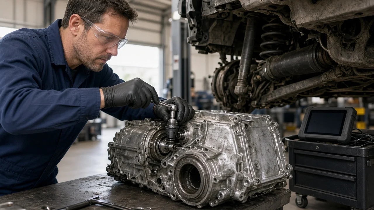
Replacing the output speed sensor on an Allison automatic is often a short job, but only when the sensor is actually the problem. The sensor reports output shaft speed to the transmission control module, which uses it for shift timing, torque converter clutch control and, on many vehicles, the speedometer. This guide covers confirming the diagnosis, preparing safe access, removing the old sensor, installing the new one and checking the result. Layouts and procedures vary between Allison models and vehicle applications.
Confirm the part and repair scope
Start by identifying the exact transmission type. Allison builds several families: the 1000 and 2000 series are common in heavy-duty pickups and medium-duty trucks, while the 3000 and 4000 series appear in buses, motorhomes and vocational trucks. The identification plate on the transmission case lists the model, serial number and part number, and the vehicle identification number adds build details. Sensor design, connector style and mounting location can differ by series, model year and drivetrain layout, since a four-wheel-drive transfer case adapter can change the rear housing. Order the replacement using those details, and compare the new sensor's body, length and connector with the old one before installing it.
Symptoms point to a bad signal, not necessarily a failed sensor. Typical signs include stored diagnostic codes in the output speed sensor circuit group, such as P0720 through P0723 on many OBD-II vehicles or Allison-specific codes read through the shift selector or a scan tool on commercial units. Other signs are an erratic or dead speedometer, harsh or mistimed shifts, and the transmission holding a single gear in a protective mode. Damaged wiring, a corroded or loose connector, a harness chafed near the exhaust, a damaged tone ring or a control module fault can produce the same codes. Before buying parts, check fluid level and condition, inspect the connector and harness, compare output speed against vehicle speed in live data, and test the sensor and circuit using the values in the service manual. Review the service history too, since recent transmission or harness work is a common source of connector problems.
Prepare tools and safe access
Get the service information for your specific vehicle: sensor location, fastener torque, connector details and the fluid level check procedure. Useful tools include a scan tool that reads transmission control module codes and live data, a multimeter, a socket set with extensions, a torque wrench, a drain pan, lint-free rags and a trim tool for stubborn connector locks. Have the replacement sensor with a new O-ring or seal, plus the correct fluid for topping off. Many Allison applications call for fluid approved to Allison TES 295 or TES 668, but confirm the fluid specification listed for your vehicle rather than assuming.
The sensor usually sits low near the rear of the case, close to the output shaft, driveshaft and exhaust. Park on level ground, set the parking brake, chock the wheels and support the vehicle on rated jack stands; never work under a vehicle held only by a jack. Let the exhaust and fluid cool, and turn the ignition off before unplugging anything. On medium-duty and commercial vehicles with air brakes, power take-off units, exhaust aftertreatment or heavy driveline parts, or wherever access requires removing a crossmember, driveshaft or large heat shields, this repair is better left to an experienced shop. The same applies if you cannot read transmission data with a scan tool.
Remove without avoidable damage
Clean the area around the sensor and connector before disconnecting anything, because dirt that falls into the open bore can end up inside the transmission. Release the connector lock carefully; plastic tabs that have been heat-cycled for years break easily. Inspect the terminals for corrosion, fluid intrusion or bent pins, since a connector fault would explain the symptoms on its own. Then remove the retaining fastener or bracket as described for your application.
The sensor is sealed in its bore by an O-ring and may be stuck from corrosion or varnish. Rotate it gently back and forth while pulling straight out. Do not pry against the case or clamp locking pliers on the sensor body, because a cracked sensor can drop pieces into the transmission and the housing can be damaged. Keep the drain pan underneath, as some fluid may seep out. Look at the sensor tip: a light film of fine particles can be found on magnetic sensors, but chunks, flakes or heavy buildup suggest internal wear that needs further diagnosis. Make sure no pieces of the old O-ring remain in the bore, and cover the opening if the new part is not ready to go in.
Install and restore the system
Fit a new O-ring if one is not already installed and lubricate it lightly with clean transmission fluid. Insert the sensor straight into the bore by hand, with the mounting tab and connector oriented the same way as the original. It should seat flush without force; a sensor that will not seat may be the wrong part or may be blocked by debris or an old seal. Tighten the fastener to the torque in the service manual, since overtightening can crack the sensor tab or the housing.
Plug in the connector until the lock engages, reattach any harness clips and route the wiring along its original path, clear of the exhaust and moving driveline parts. Reinstall any shields you removed. Top off fluid using the procedure for your vehicle; many require the engine running and fluid at operating temperature, and some Allison units report fluid level electronically through the shift selector instead of a dipstick. Clear the stored codes. A sensor replacement normally does not need a relearn, so do not reset transmission adaptive values unless the service information calls for it.
Check the completed work
Start the engine and confirm no codes return right away. During a road test, watch live data: output speed should rise and fall smoothly with vehicle speed and agree with other speed readings, without dropouts or spikes. Drive through every gear, including torque converter lockup, steady cruising and deceleration, and pay attention to shift behavior and speedometer stability. Afterward, inspect the sensor area for leaks and recheck the fluid level.
Further diagnosis is needed if the code comes back, the signal drops out over bumps or at certain speeds, or shift problems continue even though the reading looks correct. Those patterns point toward wiring, the connector, the tone ring, the control module or an internal mechanical issue rather than the new sensor. Repair options then range from harness or connector repair to a visit to a transmission specialist or dealer with Allison diagnostic software. Record the part number and date in the vehicle's service history so future diagnosis starts with accurate information.