Allison Transmission Speed Sensor Identification
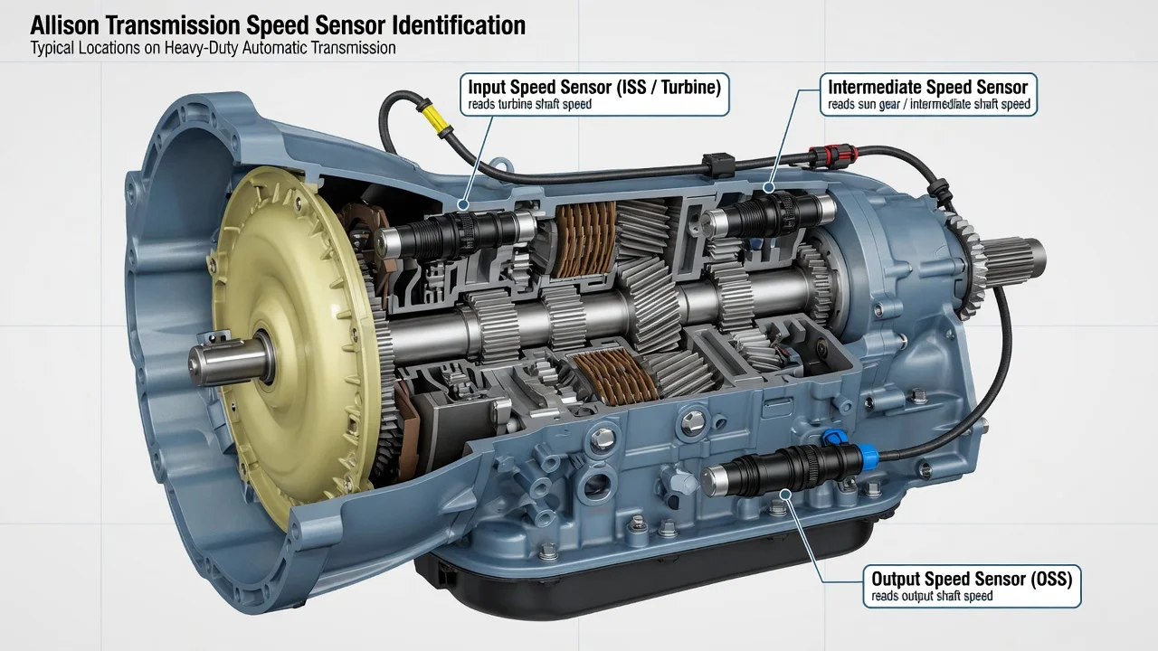
An Allison transmission uses several speed sensors, so the right one to test or replace depends on which transmission family is installed and how it is configured. Before buying a part, confirm the model from the transmission identification plate, note which sensor the stored code or live data points to, and inspect the wiring. This guide explains how to tell the sensors apart and what affects that identification.
Which speed sensor are you looking at
Most electronically controlled Allison automatics monitor at least two shaft speeds, and many monitor three: input or engine speed, turbine speed and output speed. The input sensor reports how fast the engine side of the torque converter is turning. The turbine sensor reports the speed of the shaft driven by the converter turbine. The output sensor reports the speed of the output shaft that feeds the driveline, and in many vehicles that signal also supports the speedometer and other systems.
Identifying the correct sensor takes three pieces of information: the transmission family and configuration, which sensor the diagnostic codes or live data actually implicate, and the part number or physical location. Sensors on the same transmission can look similar but differ in connector, body length or mounting position, so do not assume they are interchangeable. Keep in mind that a code or symptom points to a signal or circuit problem, not proof that the sensor itself has failed.
How Allison speed sensors work
Each sensor tip sits close to a rotating toothed or slotted part, often called a tone wheel or reluctor. As the teeth pass the tip, the sensor produces a pulsing signal whose frequency rises with shaft speed. Many transmission speed sensors are magnetic pickup, or variable reluctance, units that generate their own alternating signal and usually have two wires. Others are Hall-effect designs that need a supply voltage and usually have three wires. Which type is fitted depends on the application, so check the service information for your unit.
The control module compares these speeds constantly. Input versus turbine speed shows torque converter slip and lockup clutch operation. Turbine versus output speed reveals the actual gear ratio, which the module uses to time shifts and confirm that clutches have engaged. If one signal drops out or disagrees with the others, the module may set a code, turn on a warning light and switch to a protective mode that holds a fixed gear. That is why a single weak signal can change shift behavior so noticeably.
What changes the answer
Transmission type matters most. The Allison 1000 and 2000 series family appears in heavy-duty pickups, vans and medium-duty trucks, and the 1000 series is widely known from heavy-duty GM pickups. The 3000 and 4000 series serve larger trucks, buses and specialty vehicles. Sensor count, location, connectors and part numbers can differ between families, control generations and model years, and sometimes between vehicle manufacturers using the same basic transmission.
Drivetrain configuration also changes fitment and access. Two-wheel-drive and four-wheel-drive versions often have different output ends because of the tailhousing or transfer case, which can move the output sensor or make it harder to reach. Power takeoff units, retarders on commercial transmissions, heat shields and frame-mounted components can all affect access. Confirm the part using the transmission model and serial number from the identification plate along with the vehicle identification number, rather than the vehicle model alone.
The diagnostic path varies too. Light-duty applications commonly report generic OBD-II powertrain codes through the vehicle diagnostic port, such as P0715 for an input or turbine speed sensor circuit and P0720 for an output speed sensor circuit, with related codes for range or intermittent faults. Commercial applications may use manufacturer-specific codes or network messages, and some can display stored codes through the shift selector. Look up the exact code definition for your vehicle before deciding which sensor is involved.
What the owner can do before replacing a sensor
Start by recording every stored code, any freeze frame data and the conditions when the problem appears: cold or hot, over bumps, after rain or washing, or only at certain speeds. If your scan tool shows live data, compare the speed readings while driving steadily in a known gear. One reading that drops to zero, cuts in and out, or spikes while the others stay smooth narrows the search considerably.
Next, inspect the wiring and connector. Look for corrosion, bent or pushed-out pins, fluid inside the connector, a harness chafed against the frame or exhaust, and a loose sensor mounting. Magnetic sensor tips can collect fine metallic debris; finding debris on a removed sensor is a reason to check fluid condition and service history, not just to clean it and reinstall. If the service information gives a resistance range or signal test, compare your readings against that specification using the stated procedure.
If replacement is justified, match the part number to the transmission identification, use a new seal or O-ring if specified, and tighten the retaining bolt to specification. Some fluid can escape when a case-mounted sensor is removed, so check the level using the procedure for your model and top up only with fluid that meets the listed fluid specification, such as an Allison-approved TES-295 or TES-389 fluid where called for. Clear the codes and road test to confirm the fix.
Limitations and next step
General guidance cannot replace service data for your exact transmission, because sensor locations, test values and code definitions vary. A failed sensor shares symptoms with damaged wiring, a faulty control module, software issues, low or degraded fluid, and internal mechanical problems such as worn clutches that create ratio errors. Replacing a sensor without confirming the fault can leave the real cause in place.
Get professional help if the transmission repeatedly enters a protective mode, ratio or clutch codes appear alongside sensor codes, the fluid contains debris, or the job requires removing a transfer case, heat shields or lifting a heavy vehicle. A transmission shop with a suitable diagnostic tool can read transmission-specific data, perform any required adaptive relearn and compare repair options, from connector or harness repair to sensor replacement or internal work. Bring the transmission identification details, the recorded codes and your service history to speed up diagnosis.