Allison Transmission Input Speed Sensor Identification
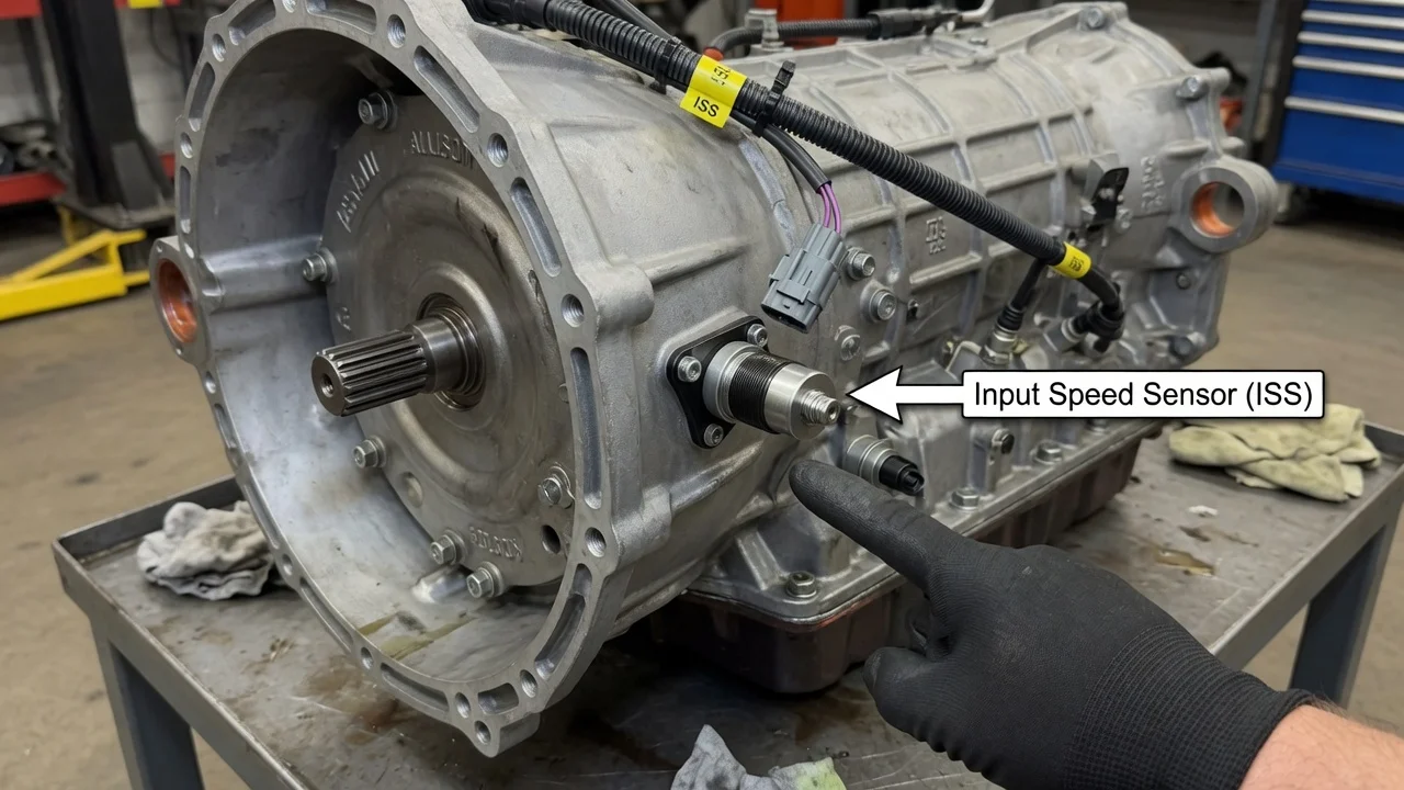
The input speed sensor on an Allison automatic tells the transmission control module how fast the turbine shaft is turning. Identifying the right one matters for two reasons. Allison builds several transmission families, each with its own sensor locations, connectors and part numbers. And a speed-sensor code does not by itself prove the sensor has failed. This guide explains how to find and confirm the correct input sensor for your unit and how to approach related symptoms without guessing.
Short Answer: Identifying the Input Speed Sensor
Allison service literature usually calls the input speed sensor the turbine speed sensor. It reads the speed of the transmission's input shaft, which is driven by the torque converter turbine. To identify the correct sensor, start with the transmission rather than the vehicle. The Allison identification plate on the case lists the transmission model, serial number and assembly part number. Those details determine which sensor fits and where it is mounted. For factory-installed units, the vehicle VIN adds the original build information. Most electronically controlled Allison transmissions have separate sensors for input (turbine) speed and output speed, and many also have an engine speed sensor. These sensors can look alike, so confirm the mounting position against service information for your exact model. Where the label or stamping on the installed sensor is still legible, match that part number as well.
Identifying the sensor is not the same as diagnosing it. A diagnostic code that points to the input speed signal means the control module saw a problem with that circuit or with the reading it received. The sensor itself is one possible cause. Others include damaged wiring, a corroded or loose connector, a control module fault, or an internal mechanical condition that makes the speed reading implausible. Treat the code as the starting point for testing, not as proof that the part is bad.
How the Input Speed Sensor Works
The sensor is mounted close to a toothed or slotted rotating member that turns with the turbine shaft. As the teeth pass the sensor tip, the sensor produces a pulsed signal, and the pulse frequency rises with shaft speed. Many Allison speed sensors are magnetic pickup types that generate their own alternating voltage. Designs can differ between applications, so electrical test values should come from the service information for your unit rather than from a general rule.
The control module compares input speed with engine speed and output speed. From those comparisons it calculates torque converter slip, confirms that the correct clutches have applied, checks the actual gear ratio, and manages shift timing and quality, including adaptive learning of clutch fill. If the input signal drops out, becomes erratic, or no longer matches the other speeds, the module can set a code. Depending on its calibration, it may also limit operation, for example by holding a fixed gear so the vehicle can still be moved. That is why input speed problems often show up as harsh or delayed shifts, flare between gears, converter clutch issues, or a sudden refusal to upshift.
What Changes the Answer: Model, Controls and Installation
Allison transmission families cover a wide range of vehicles. The 1000 and 2000 series appear in heavy-duty pickups and medium-duty trucks. The 3000 and 4000 series are used in heavier trucks, buses, motorhomes and vocational equipment. Several things can differ between families, and sometimes within one family across control generations and model years: sensor location, connector style, sensor length, seal design and part number. Allison has also superseded parts over time, so the number on an old sensor may have been replaced by a newer one. A parts source should confirm this against the transmission serial number.
The installation also matters. In a pickup where the transmission was installed at the factory, the speed sensors are integrated with the vehicle's powertrain control system, and the vehicle maker's service information applies. On many commercial chassis, the transmission uses Allison controls with their own code structure and diagnostic software, and codes may appear on a shift selector display or through a dedicated tool. Light-duty vehicles commonly report generic codes such as P0715 for the input or turbine speed sensor circuit, with related codes such as P0716 for range or performance and P0717 for no signal. Commercial applications may report different codes for a similar fault. A rebuilt, exchanged or swapped transmission may not match the vehicle's original build, so the plate on the transmission in the vehicle now is a more reliable reference than the VIN alone.
What the Owner Can Do
Start by recording the transmission model, serial number and assembly part number from the identification plate, and photograph the plate before it gets dirtier. Read the stored codes and, if your tool allows, save the freeze frame data. Note exactly how the shift behavior changes: whether it happens cold or hot, at a particular road speed, after driving in rain or washing the chassis, or only under load. On many vehicles the speedometer is driven from output speed data. A sudden erratic speedometer therefore points toward the output side more than the input side, which helps separate the two sensors. With a scan tool that shows live data, compare reported input speed with engine speed in a steady gear. A reading that drops to zero or jumps while the vehicle is moving smoothly is useful evidence for the technician.
Inspect what you can see safely. Check that the sensor connector is fully seated and locked, look for green corrosion or fluid inside the connector, and follow the harness for chafing, melted insulation near exhaust parts, or damaged retaining clips. Check the fluid level and condition using the procedure for your transmission. Allison procedures differ: some use a dipstick with hot and cold ranges, and some applications offer an electronic level check. Use the fluid specification listed for that transmission. Review the service history for recent fluid service, rebuilds, harness repairs or software updates, since any of these can affect speed signals.
Before buying a replacement, match the part number, connector shape and seal against the original, and choose a supplier that can verify fitment by serial number. If the sensor is removed, look at the tip. Heavy metallic debris on a magnetic sensor can indicate internal wear and should be reported rather than simply wiped off. After any repair, clear the codes and road test under the conditions that caused the original fault. If the same code returns with a new sensor installed, the cause lies elsewhere in the circuit or the transmission.
Limitations and Next Step
Confirming a failed input speed sensor takes information this guide cannot supply for every unit. That includes the wiring diagram for your vehicle, the specified sensor resistance or output, connector pin locations, and a scan tool that can read the correct control module. Several repair options can resolve an input speed code: replacing the sensor, repairing the harness or connector, updating or reprogramming the control module, or correcting an internal transmission problem. Choosing among them depends on test results, not on the code alone.
Seek professional help in any of these situations: the transmission is under warranty, the vehicle is a commercial unit where downtime and correct parts matter, the code persists after basic checks, or shift behavior is severe enough to affect safe driving. A dealer or Allison-authorized service location can look up the exact sensor for your serial number, read Allison-specific codes and data, and test the circuit to factory specifications. Bring the identification plate details, your recorded codes and your notes on when the symptoms appear. That information shortens diagnosis and reduces the chance of replacing the wrong part.