Freightliner Transmission Speed Sensor Identification
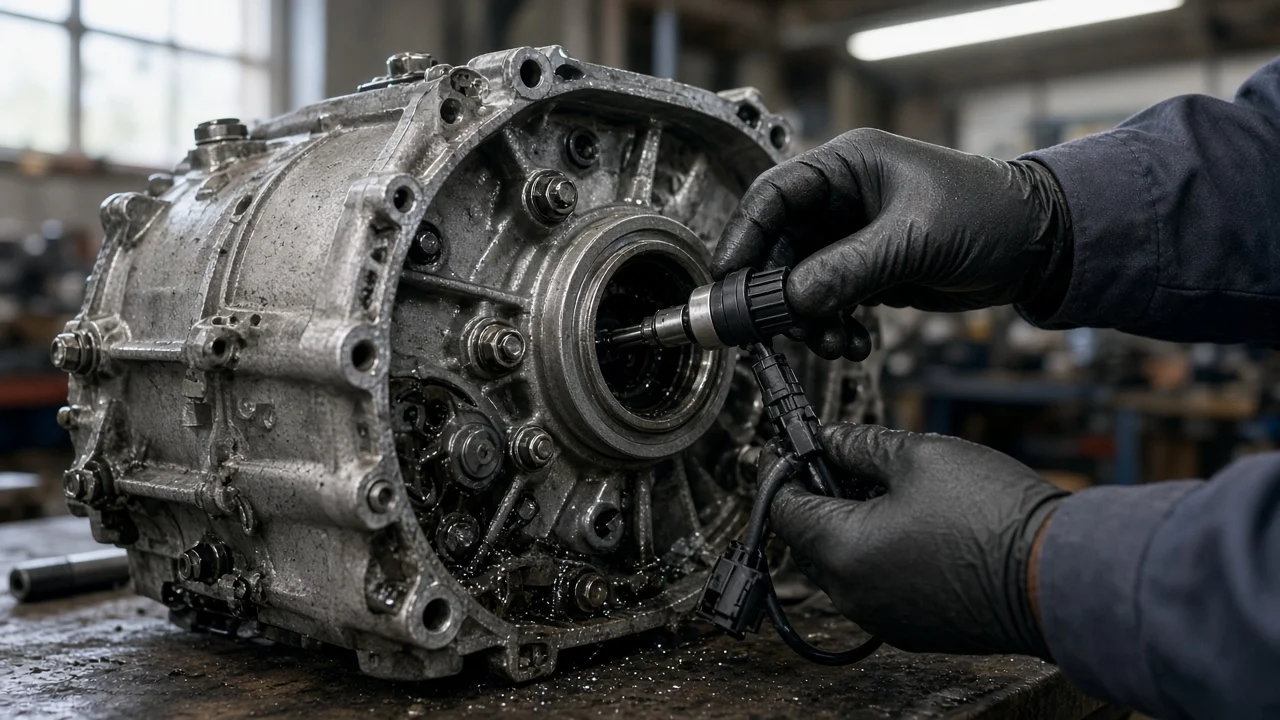
There is no single Freightliner transmission speed sensor. Depending on the gearbox, a truck may have one output speed sensor or several sensors reading input, main shaft, countershaft or turbine speed. To identify the right one, start with the transmission, not the truck model. That helps you order a part that fits, read diagnostic codes correctly and avoid replacing a sensor that was never at fault.
Short answer: identify the transmission first
To find the correct speed sensor on a Freightliner, you need two facts: the exact transmission installed and the sensor position you are dealing with. Freightliner models such as the Cascadia, Columbia, Coronado and M2 have been built with Eaton Fuller manual gearboxes, Eaton automated transmissions, Allison automatics and Detroit DT12 automated manuals, among others. Each transmission family has its own sensor layout, connector styles and part numbers. The transmission identification tag on the case lists the model and serial number, and the truck's build data shows the factory-installed transmission. With that information and the sensor's location on the case, a dealer or parts supplier can confirm fitment.
Be careful with the diagnosis. A speed-related code or an erratic speedometer only means a speed signal is missing, implausible or out of range. It does not prove the sensor has failed. Damaged wiring, a corroded connector, a damaged tone wheel or a control module problem can produce the same complaint.
How transmission speed sensors work
Most transmission speed sensors read a toothed wheel, gear or tone ring as it turns past the sensor tip. Two designs are common. A magnetic pickup, also called a variable reluctance sensor, usually has two wires and generates its own alternating signal; both frequency and voltage rise with shaft speed. A Hall-effect or active sensor usually has three wires for power, ground and signal. It needs a supply voltage and produces a switched, square-wave signal. In both cases, the control module counts pulses and converts them into shaft speed.
Output shaft speed is often the source of vehicle speed. It feeds the speedometer, cruise control and engine road speed limiting. In automated and automatic transmissions, the controller also compares input and output speeds to work out the current gear ratio, detect clutch slip and time shifts. That is why a bad signal can change shift behavior, not just the speedometer reading. Speed data is commonly shared over the truck's J1939 data network, so one faulty signal can cause complaints in several systems at once.
Sensor positions by transmission type
On Eaton Fuller manual transmissions, the speed sensor most owners deal with is the output speed sensor. It sits toward the rear of the transmission near the output shaft and yoke area. It reads a tone wheel on the output side and commonly serves as the vehicle speed source. Many manual setups have no separate input sensor for the driver to worry about.
Automated manual transmissions, such as Eaton UltraShift-type units and the Detroit DT12, use several speed sensors. Typical positions are the input shaft, the main shaft or countershaft, and the output shaft, because the transmission controller needs these readings to synchronize gears and control the clutch. Allison automatics typically use separate sensors for engine or input speed, turbine speed and output speed. The exact arrangement differs between the smaller series found in some medium-duty trucks and the larger series used in heavier applications.
Sensor positions are not interchangeable, even within one transmission. Write down exactly where the sensor sits, how it is retained, and the connector shape and pin count. Two sensors that look alike can differ in body length, tip design, sealing and electrical characteristics, and a sensor that plugs in can still be wrong for that position.
What changes the answer
Several factors can change which sensor your truck needs. Model year and transmission revision matter, because manufacturers may change sensor design, connectors or harness routing during production. A truck that has had its transmission replaced or swapped may no longer match its build record, so trust the tag on the transmission over paperwork. Changes in tire size or axle ratio affect speedometer calibration rather than the sensor itself. That is a common reason for a wrong speed reading that a new sensor will not fix.
Service history is worth reviewing. Recent clutch work, transmission removal, or output seal or yoke service can disturb a sensor, its air gap or its connector. Fluid condition also matters. Metal particles in the fluid can collect on a magnetic sensor tip and distort its signal. Worn or incorrect fluid, meaning fluid that does not meet the transmission's fluid specification, can change shift quality in ways that resemble a sensor problem. Checking fluid level and condition is a reasonable early step on automatic transmissions.
What the owner can do
Start by collecting information. Record the transmission tag details and the VIN. Then read active and inactive diagnostic codes with a heavy-duty scan tool that supports J1939. Note the SPN and FMI for each code and which module reported it. For example, SPN 191 refers to transmission output shaft speed and SPN 161 to transmission input shaft speed. The FMI indicates whether the signal is erratic, missing or out of range. Interpret codes according to the reporting module, because manufacturer-specific codes also exist.
Next, inspect the sensor and wiring with the engine off, the parking brake set and the wheels chocked. Check the connector for corrosion, broken locking tabs and pushed-back pins. Follow the harness for chafing at the frame rails, crossmembers and near exhaust components, and confirm the sensor is secure. If you remove the sensor, inspect the tip. Heavy metal debris is worth noting because it can point to internal wear that needs further investigation, beyond a sensor swap.
Electrical checks depend on sensor type. A two-wire magnetic sensor can be checked for resistance and for AC output while the shaft turns, compared against the specification for that particular transmission. A Hall-effect sensor needs the correct supply voltage, and its signal is best checked with an oscilloscope or the manufacturer's diagnostic software. Use back-probing or proper test leads rather than forcing probes into terminals. Live data is also useful: if transmission output speed drops out while ABS wheel speeds stay steady, the fault is likely in the transmission speed circuit. Repair options include cleaning and reseating a connector, repairing a damaged harness section, replacing the sensor with one matched to the transmission model and serial number, or fixing an underlying mechanical issue. After any repair, clear the codes, road test the truck and confirm the speed signal is stable in live data. Some automated and automatic transmissions may require a calibration or relearn procedure after certain repairs. Follow the manufacturer's procedure for your unit.
Limitations and when to get professional help
This article describes general patterns. Exact sensor positions, electrical specifications, connectors and test procedures vary by transmission model and revision, so use the service information for the unit in your truck. If the transmission tag is missing or unreadable, a dealer can often confirm the installed transmission from the VIN and build data.
Get professional help if several speed codes appear at once, the transmission goes into a fail-safe or limited mode, shift complaints continue after a sensor replacement, or codes point to the transmission controller or data network. A dealer or transmission specialist with manufacturer software can view all speed signals together, run guided tests and complete any required calibration. For a truck in commercial service, that is often cheaper than repeated parts replacement and unplanned downtime.