Eaton Transmission Speed Sensor Identification: Locations and Fitment
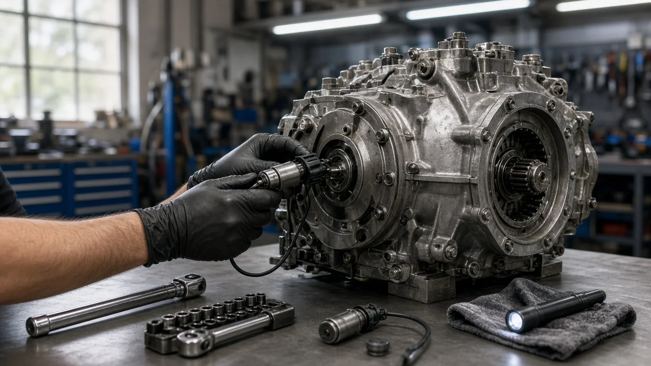
Finding the right speed sensor on an Eaton transmission starts with knowing exactly which transmission you have. Fuller manual gearboxes typically carry a single output shaft speed sensor. Automated models such as AutoShift, UltraShift and Endurant rely on several sensors that feed the transmission controller. This guide explains where those sensors usually sit and what information identifies the correct part. It also covers how to approach a speed signal fault without assuming the sensor itself has failed.
The short answer
On most Eaton Fuller transmissions, the speed sensor owners ask about is the output shaft speed sensor. It is usually mounted at the rear of the transmission, near the output yoke. It reads a toothed tone wheel that turns with the output shaft. Its signal gives the engine or vehicle controller road speed, which drives the speedometer, cruise control and road speed governing. Automated Eaton transmissions add sensors for input shaft speed and, on many models, main shaft speed. The controller compares these shaft speeds during shifts.
To identify the correct sensor, start with the tag on the transmission case and record the full model and serial number. Then note the part number on the sensor body, the connector style and how the sensor is retained. The model tag is the most reliable starting point because Eaton has produced many variants. A sensor that fits one model or production period may not fit another, even when the transmissions look similar.
How an Eaton speed sensor works
Most Eaton speed sensors are magnetic pickups. As the teeth of a tone wheel pass the sensor tip, they disturb a magnetic field and induce an alternating voltage. The frequency of that signal rises with shaft speed. The receiving controller converts the pulses into revolutions per minute using a known tooth count. The signal depends on the gap between the sensor tip and the tone wheel. Correct installation depth and a clean tip therefore matter as much as the sensor's internal condition.
On a manual Fuller transmission, the engine control module uses the output speed signal mainly for vehicle speed. On automated transmissions, the transmission controller uses input, main shaft and output speeds together. From them it calculates gear ratio, confirms engagement, synchronizes shafts and decides when to shift. A missing or erratic signal from any of these sensors can change shift behavior. The transmission may hold a gear, refuse to engage or set diagnostic codes. Which of these happens depends on the affected sensor and how the controller is programmed to respond.
What changes the answer
Transmission type is the biggest variable. A manual Fuller ten, thirteen or eighteen speed is a different case from an AutoShift, an UltraShift or UltraShift PLUS, or an Endurant. The number, location and design of the sensors differ between these families. Some older vehicles used a mechanical speedometer drive instead of an electronic sensor. Some systems also compare transmission output speed with wheel speed data from the antilock braking system, which affects how a fault shows up.
Fitment also depends on details that are easy to overlook: sensor length and body style, threaded or bracket mounting, and connector type. Another detail is whether the tone wheel tooth count matches what the controller is programmed to expect. Truck manufacturers may wire or program the same Eaton transmission differently. The chassis builder's documentation can therefore matter as much as the transmission tag. Service history counts too. A previous rebuild, replacement output yoke or swapped transmission can leave parts that no longer match the original build records.
What the owner can do
Start by writing down the following: the transmission model and serial number; the vehicle make, model and year; and any diagnostic codes stored in the engine or transmission controller. Under the J1939 standard, transmission output shaft speed is reported as SPN 191 and input shaft speed as SPN 161. The accompanying failure mode identifier indicates whether the problem looks like an open circuit, a short or an erratic signal. Eaton automated transmissions may also display their own fault codes. Read these with the service tool or literature for that specific model.
With the engine off and the vehicle secured, inspect the sensor and harness. Look for a loose or backed-out sensor and chafed wires near the crossmember or driveshaft. Also check for corroded connector pins and metal debris on the sensor tip. If you remove the sensor, check the tip for damage that suggests contact with the tone wheel. If the tone wheel is visible, inspect it for missing or bent teeth. If removal opens the case, use a new seal where specified and confirm the fluid level afterward. Use the fluid specification listed for your transmission.
Resistance and output voltage checks are useful, but the acceptable values come from the service information for your exact sensor. Do not rely on figures from a different model. Speedometer faults, cruise control dropping out or unusual shifting can also come from wiring, the controller or configuration settings. A code or symptom alone does not prove the sensor has failed. Before ordering a replacement, compare its part number and connector with the original.
Limitations and next step
This overview covers general patterns across Eaton transmissions, not the exact procedure for any one model. Sensor locations, part numbers, test values and replacement steps vary by transmission family, production period and truck manufacturer. Confirm them in the service literature that matches your model tag and vehicle. If the sensor tests within specification but the codes return, the next step is a wiring and controller diagnosis rather than another sensor.
Professional help is the better choice in three situations: an automated transmission is involved, the codes point to more than one speed signal, or the controller needs reprogramming or recalibration after a repair. A shop with Eaton diagnostic software can view live shaft speeds and compare them while driving to pinpoint which signal is wrong. That is often faster and cheaper than replacing parts in sequence. It also keeps your repair options clear before you commit to a sensor, harness or controller replacement.