Eaton Fuller Transmission Speed Sensor Identification
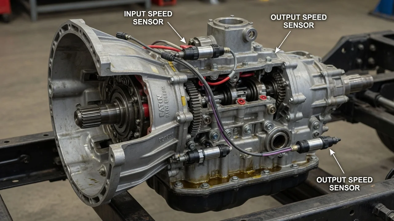
Identifying the speed sensor on an Eaton Fuller transmission starts with knowing which transmission is in the truck. A conventional manual Fuller box usually carries one output speed sensor at the rear housing. Automated versions use several sensors that feed the transmission controller. This guide explains how to tell them apart, how they work, what changes from one configuration to another, and what to check before buying a replacement or condemning a sensor that may not be at fault.
Which speed sensor does your Eaton Fuller have?
On most manual Eaton Fuller transmissions, the speed sensor is an output shaft speed sensor. It is mounted in the rear bearing cover or output housing, close to the output yoke, and reads the teeth of a tone wheel that turns with the output shaft. Its signal typically goes to the engine control module, the instrument cluster or both, where it becomes road speed for the speedometer, cruise control and road speed limiting.
Automated Eaton Fuller models, such as AutoShift and UltraShift families, rely on more than one speed signal. They commonly use an input shaft sensor, a main shaft sensor and an output shaft sensor, although the exact set depends on model and generation. In those transmissions the sensors are central to shift control, not just the speedometer. The reliable way to identify any of these sensors is by the transmission model number on the case tag and the part number on the sensor itself, not by appearance, because several sensors look alike but differ in length, thread, connector or calibration.
How the speed sensor works
Most Eaton Fuller speed sensors are magnetic pickups. Inside the body sits a permanent magnet wrapped by a coil of wire. As each tooth of the tone wheel passes the sensor tip, the magnetic field changes and the coil produces a small alternating voltage. The faster the shaft turns, the higher the frequency of that signal. The receiving module counts the pulses and, using the known tooth count plus the programmed axle ratio and tire size, converts them into shaft speed or vehicle speed.
Because the signal depends on the gap between the sensor tip and the teeth, mounting position matters. Too large a gap can weaken the signal at low speed, while contact with the tone wheel can damage the sensor. Metal particles collecting on the magnetic tip can also distort the reading. Some older trucks used a mechanical speedometer drive instead of an electrical sensor, and some applications may use a different sensor design, so confirm what is fitted before assuming a test method applies.
What changes the answer
Transmission type is the biggest variable. A manual box usually has one sensor serving road speed, while an automated unit has several serving the transmission controller, and a fault in one of them can alter shift behavior or prevent shifting entirely. Within each family, model series and production period affect housing design, sensor location and part number. The truck manufacturer also matters, because the chassis wiring decides which module reads the output signal and how it is calibrated.
Mounting style changes fitment and installation. Some sensors thread into the housing and are set by a specific installation procedure, while others are flange-mounted with a fixed depth and an O-ring seal. Connector shape, body length and thread size differ between versions. Service history is another factor: if the transmission, rear bearing cover or output components were replaced, the sensor on the truck may not match the original build record, so the part in hand is a better guide than the vehicle's documentation alone.
What the owner can do
Start with identification. Read the model and serial number from the Eaton tag on the transmission case, then locate the sensor and note any part number stamped or printed on its body, its mounting style and its connector type. Record the symptoms precisely: an erratic or dead speedometer, cruise control dropping out, road speed codes stored in the engine module, or, on automated units, harsh shifts, missed shifts, a stuck gear or a transmission warning lamp.
Read diagnostic codes with a tool that can access the relevant modules, and note which shaft the code refers to and whether it describes an open circuit, a short, an erratic signal or a signal that does not agree with other speeds. Then inspect the wiring harness and connector for chafing, corrosion, loose terminals and damage near the driveline, where harnesses often rub. If the sensor is removed, look at the tip for metal debris; heavy debris is worth noting because it may point to internal wear rather than a sensor problem.
A resistance check of the sensor coil is only meaningful against the published value for that exact part, so obtain the specification rather than relying on a generic number. When reinstalling, follow the correct gap or depth procedure for that sensor style and fit a new seal if required. If any oil was lost, check the level and top up with fluid that meets the specification listed for that transmission. Repair options range from replacing a connector or harness section to replacing the sensor, or further inspection if the tone wheel itself is damaged.
Limitations and next step
A speed sensor code identifies a circuit or signal problem, not a confirmed failed part. The same symptoms can come from wiring, connectors, a damaged or loose tone wheel, incorrect calibration of tire size or axle ratio, excessive output shaft movement, or a fault in the module reading the signal. Replacing the sensor without testing the circuit may leave the actual cause in place, and on automated transmissions an incorrect part can create new shift complaints.
Exact resistance values, installation gaps, torque figures and calibration steps depend on the transmission model and the truck build, so use the manufacturer's service information for that combination. Automated transmissions may also need a service tool to clear codes or confirm the repair. If codes persist after the wiring checks out, if multiple speed signals are affected at once, or if metal debris appears on the sensor, have a transmission specialist or the truck dealer diagnose the unit before further parts are replaced.