Brake Master Cylinder Repair: What the Job Involves
What this job covers
On a conventional hydraulic brake system, the master cylinder is the unit at the pedal that turns foot force into fluid pressure in the brake lines. In a workshop, “repair” almost always means removing that unit, fitting a new or remanufactured replacement, and bleeding the hydraulic circuits until the pedal is firm and both circuits hold pressure. A seal-kit rebuild of the original bore is a narrower job that still exists for some serviceable housings, mainly older or heavy-duty designs with a refinishable bore. Many later passenger-car units use aluminium or composite bores meant to be replaced as an assembly. This article describes firewall-mounted tandem master cylinders used with a vacuum, hydraulic, or mechanical booster. Some later cars and light vehicles use electric brake boosters or brake-by-wire pressure generators; those assemblies follow a different procedure and sit outside this scope. Fastener torque, pushrod setting, fluid grade, and bleed order are vehicle-specific and must be taken from the service information for that model year, brake package, and market.
How the master cylinder builds pressure
Pressing the brake pedal moves a pushrod into the master cylinder. That rod drives two pistons in series inside a shared bore—the tandem, or dual-circuit, layout used on modern passenger vehicles so that a leak in one circuit still leaves another circuit able to slow the vehicle. Each piston carries rubber cup seals. As a piston moves, it closes a compensating port (a small passage back to the reservoir) and then pressurizes its circuit. Releasing the pedal lets the pistons return under spring force; the compensating ports reopen so fluid can expand or contract with temperature and so the cups can re-centre. The reservoir above the bore stores extra fluid and keeps the bore flooded. A vacuum booster, where fitted, sits between the pedal and the master cylinder and multiplies pedal force; the master cylinder itself remains the hydraulic pump.
Internal seal wear lets fluid slip past a cup instead of building pressure. The usual result is a pedal that sinks under steady foot pressure, a long or spongy pedal, or a falling reservoir level with little or no puddle at a caliper or hose—fluid can leak into the booster at the rear seal. Glycol brake fluids absorb moisture, and water-laden or dirty fluid accelerates cup and bore wear. Those failure modes are why the job is a hydraulic-system repair: the new unit only works if the circuits are full of the specified fluid and free of air, and if the rest of the system is not feeding debris or moisture back into the new seals.
Rebuild kit or a complete unit
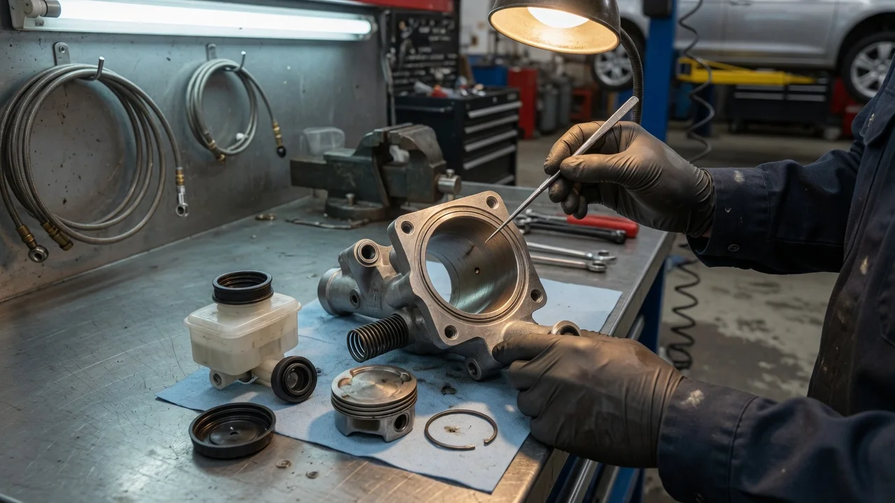
A rebuild kit typically supplies cups, O-rings, residual-pressure valves where used, and sometimes a reservoir grommet or cap seal. The old bore must be within the maker’s diameter and finish limits after cleaning; scoring, pitting, or a worn step at the cup travel usually rules out a kit. Remanufactured units are bored or sleeved and assembled to those limits. New units replace the original housing. The vehicle’s parts catalogue and the unit’s service literature decide whether a kit is offered. There is no universal rule that every master cylinder is rebuildable.
Use a kit only when the housing is specified as rebuildable and the bore inspects within the published limits. Fit a new or remanufactured complete unit when no kit is listed, the bore is damaged, or an integral reservoir, cap sensor, or proportioning feature is faulty. Match port layout, bore size, and reservoir type (single or dual, with or without a fluid-level switch) to the original. A similar-looking unit with different compensation or stroke can leave a dragging or long pedal. If the fluid is heavily darkened, sludged, or contaminated with petroleum products, plan to flush the lines and inspect calipers, wheel cylinders, and hoses. A new master cylinder on a dirty system often fails again.
Prerequisites, tools, and shop limits
Work from the vehicle’s service information for that model year, powertrain, and brake package. Fastener torque, pushrod length or lash, fluid specification, and bleed order are published settings for that vehicle; they are not interchangeable across makes. Common glycol grades are DOT 3, DOT 4, and DOT 5.1—the correct grade is the one printed in the owner information and on the reservoir cap. Confirm whether the vehicle requires a scan-tool-controlled ABS or stability-control bleed after the master cylinder is changed. If the pedal is already hard with the engine off, the booster is silent, or the ABS or brake warning lamps are on, diagnose those systems before changing the master cylinder. A stored fault code is a reason to investigate, not proof that the master cylinder has failed.
Typical tools include flare-nut (line) wrenches sized to the tube nuts, a pedal prop, a syringe or bulb dedicated to brake fluid, a catch container, a bench-bleed kit or spare lines that can loop from the outlet ports back into the reservoir, fresh specified brake fluid from an unopened container, and a torque wrench. Safety glasses and chemical-resistant gloves belong in the same kit: glycol fluid is an irritant and it strips paint. A pressure or vacuum bleeder speeds the system bleed and still follows the manufacturer’s sequence. Stop and use a workshop if the tube nuts are seized or rounded, the booster or pedal bracket is damaged, an electric booster or integrated modulator is involved, or a firm, high pedal cannot be obtained after a complete bleed.
Steps of the job
The sequence below is the usual shop order for a conventional tandem master cylinder. Insert the vehicle’s torque figures, pushrod setting, and bleed procedure at the points noted. Treat the factory steps for the specific vehicle as the controlling document.
Park on level ground, chock the wheels, and allow the system to cool. Record the reservoir fluid level and colour, and note line routing. If the vehicle must be raised to reach the unit, support it on stands after lifting. Disconnect the battery only if the service information requires it; some fluid-level sensors and electric boosters need that step. Remove enough cowl or ducting to reach the reservoir and tube nuts without stressing the lines. Siphon most of the fluid from the reservoir so it does not spill onto paint when the unit comes off. Keep fluid off bodywork and wash any splash immediately. Discard the drained fluid; it is not reused. Clean the tube nuts, then crack them with a flare-nut wrench. Cap the open lines and the master-cylinder ports so dirt cannot enter. Use a pedal prop only if the procedure calls for it. Separate the pushrod from the booster or pedal. Some designs use a clip and pin; others thread the rod or set it with a locknut. Measure or mark the existing pushrod length before disturbing it. An over-long rod can hold the compensating ports closed and drag the brakes; an over-short rod leaves a long pedal. Remove the mounting nuts and take the master cylinder off the booster or firewall. Keep the booster’s input area clean; fluid in a vacuum booster can damage the diaphragm. Compare the new or remanufactured unit to the old one: port thread and spacing, reservoir orientation, level-switch connector, and mounting flange. Transfer the reservoir only if the procedure says to, using new grommets seated with clean specified fluid rather than oil or grease. Bench-bleed the unit before it goes on the vehicle. Mount it in a vice on the flange, fit the bleed tubes from the outlets back into the reservoir, fill with the specified fluid, and stroke the primary piston slowly until the tubes show a solid stream with no bubbles. Keep the reservoir topped up so air is not drawn back in. This step is what keeps a long, spongy pedal from appearing after an otherwise correct installation. Install the unit on the booster or firewall and tighten the mounting nuts to the published torque. Reconnect the pushrod to the marked or specified length and lash. Start the brake-tube nuts by hand to avoid cross-threading, then tighten to the published value. Refit the level-switch connector and any brackets. Fill the reservoir to the marked range with fresh specified fluid. Bleed the hydraulic system in the published order. After a master-cylinder change, many ABS-equipped vehicles also need an automated bleed of the hydraulic control unit with a scan tool; air can remain trapped where a pedal bleed cannot move it. Keep the reservoir from running empty during bleeding. Inspect every disturbed fitting and the booster face for seepage. Apply steady pedal pressure for several seconds and confirm the pedal height holds. Check that stop-lamp and brake-warning behaviour is normal with the ignition in the appropriate position. Road-test only after the pedal is firm with booster assistance as designed and warning lamps are in their normal state. Use a quiet area at low speed for the first stops. Recheck the reservoir level after the pads have seated against the rotors and the system has cooled.
How to tell the job is finished
The pedal is high and firm, and it holds height under a steady load of several seconds. The reservoir is at the full mark with the specified fluid, the cap vent is clear, and the fluid-level warning is off when the level is correct. There is no wetness at the tube nuts, reservoir grommets, or the rear of the unit where it meets the booster. The wheels turn freely with the pedal released, which confirms the pushrod is not holding the pistons off the compensating ports. ABS, brake, and related lamps complete their normal bulb check and then go out, unless a separate fault is already documented. After the first short drive and a cool-down, fluid level and fittings are unchanged.
Conditions that require a workshop
Brake fluid specification is a vehicle setting. Glycol fluids (DOT 3, DOT 4, DOT 5.1) follow the maker’s mixing rules; silicone DOT 5 is a different chemistry and is kept out of a glycol system. Fluid that has been opened and stored absorbs water and is a poor fill for a freshly repaired system. Because the tandem design is the backup if one circuit fails, both circuits must be bled and both must hold; a firm pedal on one circuit alone is an incomplete job. If the old fluid shows petroleum contamination—often swollen, soft rubber—replacing only the master cylinder will not restore the brakes. Seals throughout the system are already compromised, and the vehicle should stay off the road until the hydraulic parts are rebuilt or replaced as a set. Rounded tube nuts, a soaked vacuum booster, an electric booster or integrated hydraulic control unit, and any case where the pedal stays long after a full bleed are the usual points at which the job leaves the driveway and goes to a shop with the correct tools and service data.