ABS Wheel Speed Sensor Connectors: Identifying the Correct Replacement
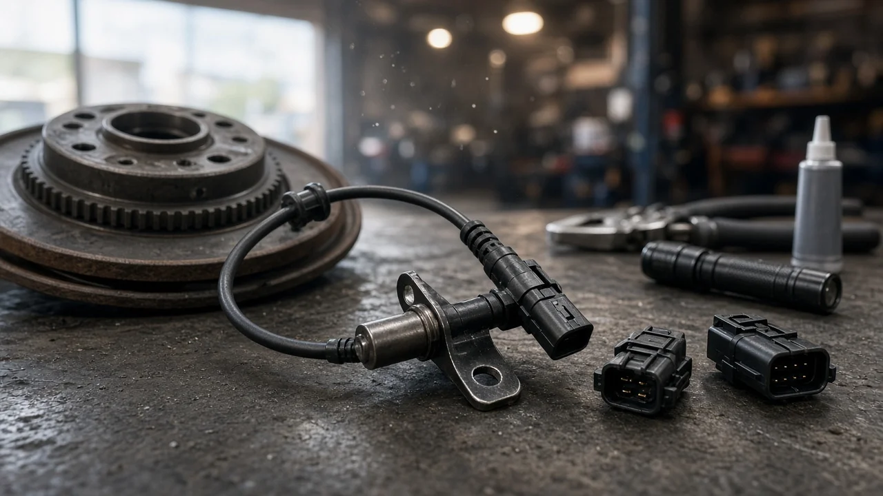
A cracked housing, corroded terminals or a broken locking tab on an ABS wheel speed sensor connector can trigger an ABS or traction control warning just as surely as a failed sensor. Buying the right replacement depends on matching the connector to your exact vehicle. You also need to confirm that the plug is actually at fault, rather than the sensor, the tone ring or wiring further along the harness. This guide covers identification, removal, installation and verification.
Confirm the part and repair scope
Wheel speed sensor connectors vary by vehicle, model year, axle position and sometimes trim or brake package. Two plugs that look alike can differ in pin count, keying, terminal size, seal design and locking style, so appearance alone is not a reliable match. Start with a VIN-based parts lookup or the manufacturer's parts catalog, and note any part number molded into the sensor body or connector housing. Then decide which side needs replacing. On many vehicles the sensor has an integrated lead and connector, so a damaged sensor-side plug means replacing the whole sensor. The harness side may be sold as a repair pigtail or only as part of a larger harness section. Some rear sensors are built into the wheel bearing hub assembly, which changes the repair entirely.
Before ordering anything, confirm that the connector is the cause. Read stored codes with a scan tool that can access the ABS module, then compare live wheel speed readings from all four wheels. The connector is the likely fault if a reading drops out when you flex the harness and the plug shows corrosion, pushed-back terminals or a loose fit. If the signal is erratic or missing and the connector is clean and tight, look instead at the sensor, tone ring, wheel bearing or wiring. Follow the service information when checking resistance or signal output. Passive and active sensors are tested differently, and probing the wrong way can damage terminals or seals.
Prepare tools and safe access
You will usually need a scan tool with ABS functions, a digital multimeter and terminal release tools that fit the connector family. A pigtail repair also needs the crimp tool and the sealed splices or heat-shrink specified for that harness. Get the vehicle-specific service information for the sensor circuit, including wire colors, connector views, routing and torque values for sensor or bracket fasteners. Do not guess these figures. Park on level ground and chock the wheels. Raise the vehicle with a suitable jack and support it on rated stands before working under it. Removing the wheel often gives better access to the sensor lead and its routing clips.
A careful owner can usually replace a plug-in sensor or connect a complete pigtail. Splicing into ABS wiring is a different matter. Some manufacturers require particular splice methods or twisted-pair repairs, and some prohibit splicing on certain circuits. A poor repair can cause intermittent faults that disable ABS and stability control. If the red brake warning is on along with the ABS lamp, stop driving the vehicle. Do the same if the pedal feels abnormal or braking behavior has changed. Have the brake system inspected professionally before you deal with the connector.
Remove without avoidable damage
Turn the ignition off before disconnecting anything. Most connectors have a primary locking tab, and many add a secondary connector position assurance lock that must be slid or lifted first. Release them as the service information describes, and pull on the housing, never on the wires. Plastic near the brakes becomes brittle with heat and cracks easily, so use steady pressure rather than prying with a screwdriver. Before you unclip anything, photograph the connector, the wire colors and the full routing path, including every clip, grommet and bracket.
The sensor lead often runs alongside the flexible brake hose and across suspension components. Keep it clear of the brake hose fittings, do not twist or kink the hose, and do not open the hydraulic system. This job does not involve brake fluid. If you are also removing a sensor, avoid hitting the tone ring or the brake rotors, and expect corrosion in the mounting bore on older vehicles. Forcing a seized sensor can break it off in the knuckle, which adds a lot of work. If you have to cut off a damaged pigtail, cut only where the instructions indicate and leave enough wire for proper splices.
Install and restore the system
Before making any connection, check that the new connector matches the old one in keying, pin count and terminal layout. On a pigtail repair, join each wire to its matching color or circuit as shown in the wiring diagram. Some active sensors are polarity sensitive and will not produce a usable signal if the two wires are reversed. Stagger the splice points so they do not form a bulge. Crimp each joint with the correct tool and seal it so moisture and road salt cannot get in. Use dielectric grease only if the manufacturer calls for it on that connector.
Press the connector halves together until the lock engages, then fit the secondary lock if there is one. Return the lead to its original clips and grommets so it cannot rub on the tire or touch the caliper or rotor. It also must not stretch as the suspension moves or the wheels steer. Turn the steering from lock to lock and check clearance. If you replaced a sensor, clean the bore and install the sensor to the depth and torque given in the service information. Set any adjustable air gap as specified. Clear stored codes with the scan tool. Some ABS modules keep the warning lamp on until a self-test, a short drive above a set speed or a scan-tool procedure is completed.
Check the completed work
When you switch the ignition on, the ABS and traction control lamps should light briefly during the bulb check and then go out. On some vehicles they go out only once the module sees wheel speed during the first drive. Drive at a steady speed in a safe area and watch the scan tool's live data. All four wheel speed readings should track closely and stay stable over bumps and through turns. A reading that drops to zero or spikes means the problem has not been fixed.
After the road test, recheck for codes and inspect the connector and its routing for movement or contact with moving parts. If a code returns with a clean, properly seated connector, further diagnosis is needed. Likely causes are a damaged tone ring, excessive wheel bearing play, a failing sensor, harness damage elsewhere or an ABS module fault. While the wheel is off, you can check the brake pads' friction material and rotor condition against the vehicle's wear limits, though that inspection is separate from the connector repair. Any change in braking performance after the work calls for professional inspection.