4L60E Valve Body Diagram and Component Identification
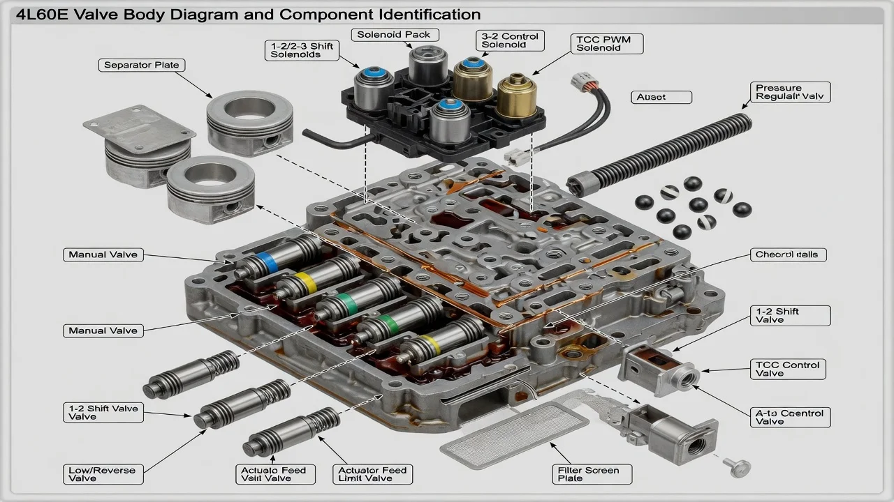
The 4L60E valve body is the hydraulic control center of GM's four-speed electronically controlled automatic. It bolts to the transmission case beneath the oil pan. A diagram helps you match each bore, solenoid and check ball location to its name, but only if it matches your exact unit. This guide explains how to identify the main components, how they work together, and what to confirm before drawing conclusions about a shifting problem.
What a 4L60E Valve Body Diagram Shows
A typical 4L60E valve body diagram is an exploded view. It shows the cast aluminum valve body, the separator plate and its gaskets, the solenoids and switches mounted to it, and the spool valves and springs held in each bore by retaining pins or plugs. Good diagrams label each valve train in order, from the outer plug or sleeve to the spring and valve, because that sequence matters during reassembly. Many also show the check ball locations on the case side and the valve body side as separate views, since those balls can fall out once the plate is removed.
Use a generic diagram to find your way around the valve body, not as an exact blueprint. GM revised the 4L60E several times during its production run. Passage layouts, separator plate holes, check ball positions and electrical parts all changed along the way. The most reliable reference is a factory service manual or rebuild diagram matched to your transmission's model year and code.
Main Components and How to Identify Them
The electrical components are the easiest to spot because they connect to the internal wiring harness. Shift solenoids A and B are on/off solenoids that, in combination, select the gear the computer commands. The pressure control solenoid, sometimes called the force motor, varies line pressure based on throttle and load. Depending on the year, you may also find a 3-2 control solenoid that manages 3-2 downshift timing. There are also torque converter clutch solenoids, which can be on/off, pulse-width modulated, or both, and which share the same internal harness. The fluid pressure switch assembly is a manifold of several pressure switches that tells the computer which range the manual valve is in. On many units the fluid temperature sensor is built into this assembly or into the internal harness.
Inside the bores are spool valves that route fluid. The manual valve connects to the gear selector through the inside detent lever and moves with each range selection. The 1-2, 2-3 and 3-4 shift valves respond to solenoid signal pressure and direct fluid to the clutches and band for each gear. Other valves shape pressure and timing rather than selecting a gear. Examples include the 3-2 downshift valve, the 4-3 sequence valve, accumulator control valves and the actuator feed limit valve. The 1-2 accumulator housing bolts to the valve body and cushions the 1-2 shift, while the 3-4 accumulator and 2-4 servo are located in the case.
The separator plate sits between the valve body and the case. Its pattern of holes meters and directs fluid, and it often carries a stamped identification code that helps confirm it matches the valve body and year. Gaskets on both sides seal the plate. Check balls are small steel or composite balls seated in pockets in the valve body or case. Each one acts as a one-way valve or as a shuttle between two circuits. Their number and locations varied by year, so photograph every ball position before lifting the plate.
How the Valve Body Controls Shifting
The pump produces fluid pressure. On this transmission the pressure regulator valve sits in the pump rather than the valve body, and it sets line pressure using input from the pressure control solenoid. Line pressure enters the valve body, where the manual valve sends it only to the circuits allowed for the selected range. The control module energizes shift solenoids A and B in a set pattern for each gear. Both are on in first, only B in second, neither in third, and only A in fourth. Their signal pressure moves the shift valves, which apply or release the clutches and band through the separator plate passages.
Shift quality depends on more than which valve moves. Accumulators, check balls, spring rates and separator plate orifice sizes control how quickly pressure builds, and the pressure control solenoid adjusts firmness for load. As a result, a worn bore, missing check ball, damaged gasket or weak spring can cause symptoms that resemble an electrical fault. An electrical fault can also resemble internal wear.
Year, Model and Fitment Differences
The 4L60E entered production in the early 1990s and later evolved into the closely related 4L65E and 4L70E. These share a general layout, but their valve bodies, separator plates, solenoids and pressure switch assemblies are not automatically interchangeable. Changes over the years included different converter clutch control strategies, revised pressure switch assemblies and temperature sensor locations, revised plates and check ball arrangements, and different harness connectors. Truck, SUV and car applications also used calibrations tied to the hardware installed.
Modifications change the picture too. A performance valve body, modified separator plate or shift kit will not match a stock diagram, and its shift behavior may be intentionally firmer. A transmission swapped from another vehicle may carry hardware that does not match the vehicle's calibration. A prior rebuild, a replaced valve body or an incorrect fluid fill can all explain behavior that a stock diagram cannot.
Reading Symptoms and Diagnostic Codes
Diagnostic codes point to a circuit or a performance condition, not to a confirmed failed part. For example, a shift solenoid performance code can come from: • a faulty solenoid; • a wiring or connector problem; • low or degraded fluid; • a sticking shift valve; • internal clutch damage; Pressure switch codes can reflect a switch fault, misadjusted range selector linkage or a hydraulic problem in the monitored circuit. When reading codes, note whether each one is current or stored, and check freeze-frame data where available.
Describe the shift behavior precisely before anyone opens the pan. Note whether you see harsh or delayed engagement, a missing gear, flare between gears, slipping under load, converter clutch shudder or a default to one gear. Also record the fluid temperature, vehicle speed and whether the issue comes and goes. These details help separate electrical problems from hydraulic ones. For example, a transmission stuck in a single gear may be in a failsafe mode caused by a lost electrical signal rather than internal damage. That still needs testing to confirm.
Practical Steps Before Ordering Parts
Start by confirming exactly what you have. GM lists option codes on a service parts label, often found in the glove box. The 4L60E is commonly identified by the code M30, while related versions use different codes. The transmission case also carries an identification tag or stamp. Check the fluid level and condition using your vehicle's procedure, since some have a dipstick and others require a temperature-specific check. Confirm the fluid specification in the owner's manual, and record any burnt smell or heavy debris on the pan magnet.
If the valve body comes out, work cleanly and slowly. Photograph the harness routing, solenoid positions and check balls first. Keep the bolts sorted by length, and remove valve trains one bore at a time so springs and valves stay in order. Inspect the bores and valves for scoring, sticking or debris, and compare the separator plate code with the reference. Match any replacement part to the model year, transmission code and vehicle, not to the name alone. Follow the factory torque and tightening sequence, because overtightening can distort the casting or plate.
Limitations and Next Step
Repair options range from replacing a single solenoid or pressure switch assembly, to reconditioning worn bores, to fitting a remanufactured valve body, to a full rebuild if clutches or the band are damaged. A diagram cannot tell you which option a specific vehicle needs. Accurate diagnosis often requires a scan tool that reads transmission data and commands the solenoids, plus electrical testing and sometimes a line pressure test. Some vehicles also need relearn procedures after repair. If codes return, the transmission slips or the fluid shows internal damage, have a transmission specialist inspect it and bring your service history.