Rack-and-Pinion Steering Linkage: Components and Operation
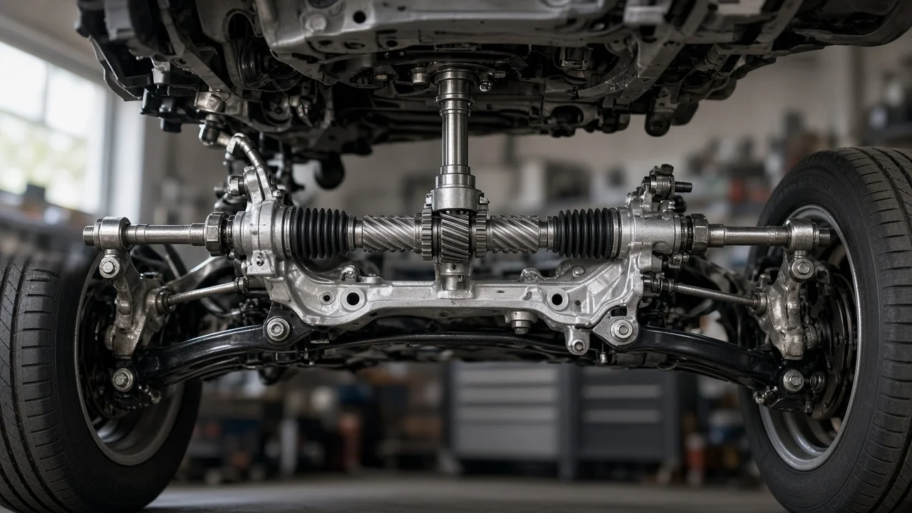
A rack-and-pinion steering linkage converts the rotation of the steering wheel into the side-to-side push and pull that turns the front wheels. It is the standard layout on most modern cars, crossovers and many light trucks because it is compact and direct, with relatively few wear points. Knowing what each part does makes it easier to describe a symptom accurately, understand what an inspection is looking for and see why work on this system usually ends with a wheel alignment.
What the linkage consists of
The linkage is a short chain of parts between the steering column and the steering knuckles. The steering shaft and intermediate shaft, usually with one or two universal joints, carry rotation down to the pinion, a small gear inside the steering gear housing. The pinion meshes with the rack, a straight toothed bar that slides inside a tube bolted to the subframe or crossmember through rubber bushings or brackets. Each end of the rack carries an inner tie rod with a ball socket, protected by a rubber or plastic bellows boot. The inner tie rod threads into an outer tie rod end. This is a sealed ball joint whose tapered stud fits into the steering arm on the knuckle. A jam nut locks that threaded connection, which is also where toe is adjusted.
Most systems add power assistance. Hydraulic units have a control valve around the pinion, a piston on the rack, a pump, and pressure and return lines. Electric power steering replaces those parts with a motor and torque sensor mounted on the column, the pinion or the rack itself. Either way, the mechanical linkage that physically positions the wheels is essentially the same.
How steering input reaches the wheels
When the steering wheel is turned, the pinion rotates and its teeth drive the rack sideways. Because the rack is a single solid bar, one end pushes outward while the other pulls inward. The tie rods transfer that motion to the steering arms, pivoting each knuckle around its upper and lower pivots, which are either ball joints or a ball joint and strut mount. The relationship between pinion and rack teeth sets how far the wheels turn for each turn of the steering wheel. Some racks use variable tooth spacing, so steering is slower near center and quicker toward full lock.
The ball joints at both ends of each tie rod let the linkage follow the wheels as the suspension moves up and down and as the knuckles swing through their arc. The geometry is designed so each tie rod travels in a path closely matching the suspension's, keeping toe nearly constant over bumps. The steering arms are also angled so the inside wheel turns slightly more than the outside wheel in a corner, reducing tire scrub. Power assist only adds force in the direction the driver is already steering. A pressure difference across the rack piston or torque from an electric motor does the extra work, while the mechanical connection stays in place.
What changes from one vehicle to another
Rack placement varies. Some racks sit ahead of the front axle centerline and others behind it, which changes whether the tie rods push or pull to steer in a given direction and how the steering arms are packaged. A few older designs use a center-take-off rack, where both tie rods bolt to the middle of the rack rather than its ends. Many full-size trucks and heavy-duty vehicles do not use rack and pinion at all. They rely on a steering box with a parallelogram or drag-link arrangement, where the parts and inspection points differ substantially.
Ride height matters too. Lowering or lifting a vehicle changes the angle of the tie rods relative to the control arms, which can introduce bump steer, where the wheels change toe as the suspension compresses and extends. Worn rack bushings and a tie rod bent by a curb strike can also alter how the linkage behaves. Hydraulic and electric systems fail differently. Hydraulic racks can leak fluid past internal or external seals, while electric systems may set warning lights or lose assist without any visible leak.
Signs of wear and what an owner can check
Common signs of linkage wear include: • Free play or a dead spot around center; • A clunk or knock when turning or over bumps; • The vehicle wandering on a straight road; • A steering wheel that sits off center after an impact; • Tire wear concentrated on the inner or outer edges; A torn boot is worth noting early, because dirt and water entering the inner tie rod socket or rack seal area accelerate wear. On hydraulic systems, look for fluid wetness at the rack ends, valve area and lines, and check the reservoir level against its markings.
A basic hands-on check requires proper vehicle support. Lift at the points specified by the manufacturer, set the vehicle on rated jack stands on firm, level ground, and never work under a vehicle held only by a jack. With the front wheels off the ground, grasp a tire at the three and nine o'clock positions and rock it in and out. Movement you can see or feel at a tie rod end, or through the boot at the inner joint, indicates joint play. Play when gripping at twelve and six usually points to wheel bearings or ball joints instead. With the wheels on the ground, have a helper rock the steering wheel back and forth a short distance while you watch each joint and the rack mounting points. Some looseness only shows up under that load.
Replacing linkage parts and alignment
Replacing a tie rod end, inner tie rod or rack disturbs the toe setting, even if you carefully measure the old and new parts or count thread turns. Matching lengths that way is only good enough to get the vehicle to an alignment shop. Have a wheel alignment done promptly afterward. For tie rod nuts, jam nuts and rack mounting bolts, use the fastener specification in the service information for your exact vehicle. Follow it on whether self-locking nuts or cotter pins must be renewed. Replace bent tie rods rather than straightening them. When fitting new boots, seat the clamps correctly and make sure the boot is not twisted at installation.
Limitations and when to get professional help
This article describes the general layout. Part designs, rack location, inspection procedures, lift points and specifications differ by make, model, year and trim. A visual and hand check can confirm obvious looseness but may miss internal rack wear, a bushing that only moves under load, or an electric assist fault that needs a scan tool to diagnose. It also cannot tell you how long a worn component will last.
Steering components directly affect control of the vehicle. Get a qualified technician to inspect it promptly, before continuing to drive, if you notice any of these: • Noticeable looseness in the steering; • A clunk together with changing steering feel; • A bent part; • A sudden loss of assist; Note when the symptom occurs and what has changed recently, such as an impact, new tires or a ride height modification. For any repair you do yourself, follow the manufacturer's service information.