Brake Fluid Level Sensor Wiring Diagram and Connector Identification
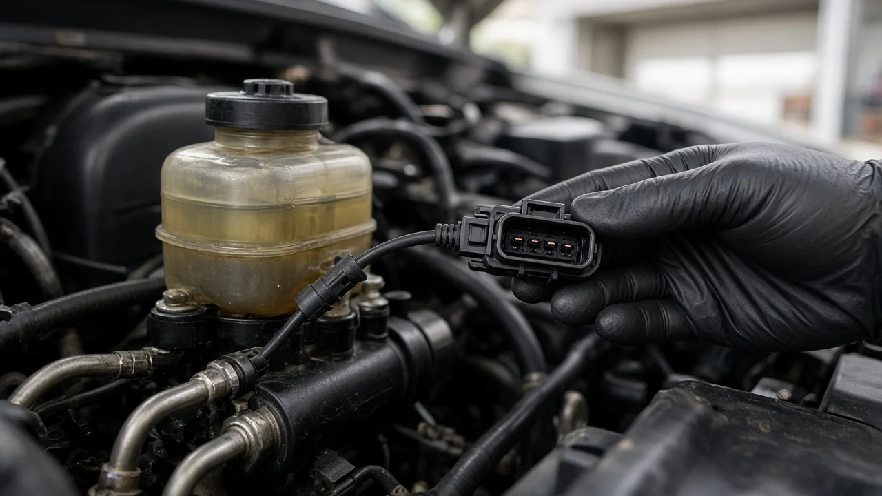
A brake fluid level sensor is usually a simple switch, but its wiring is not identical across vehicles. This guide explains how the circuit typically works, how to identify the connector at the master cylinder reservoir, and how to test it without guessing. Treat any low-fluid warning as a braking concern first and an electrical question second. The fluid level itself may be telling you something about pad wear or a leak.
The Short Answer
On most vehicles the brake fluid level sensor is a two-terminal switch mounted in or on the master cylinder reservoir. One terminal carries the signal to the warning circuit, which may be the instrument cluster, a body control module or the ABS module. The other terminal goes to ground or returns to the same module. A magnetic float inside the reservoir operates the switch when the level falls toward the minimum mark. There is no universal wiring diagram, however. Pin count, wire colors, switch logic and the module that reads the signal all vary by manufacturer, model year and trim, so the exact diagram has to come from service information that matches your specific vehicle fitment.
Before tracing wires, look at the reservoir. If the fluid is genuinely at or below the minimum line, the sensor is doing its job and the real question is why the level dropped. A wiring diagnosis only makes sense once you have confirmed the fluid level is correct and the brakes feel and work normally.
How the Level Sensor Circuit Works
Inside the reservoir, a float carrying a small magnet rides on the brake fluid. Near the bottom of its travel sits a reed switch, either in a stem that drops into the reservoir from the cap or in a housing molded into the reservoir body. When the fluid falls far enough, the magnet moves close to the reed switch and changes its state. In a typical modern setup, the module supplies a reference voltage on the signal wire and watches for it to be pulled low when the switch connects to ground. On older vehicles the switch may simply complete the ground path for a warning bulb. Either way, the result is a red brake warning lamp or a low brake fluid message on the dash.
It also helps to know why the level moves at all. As friction material wears off the brake pads, the caliper pistons sit farther out of their bores, and fluid from the reservoir fills the extra space behind them. A slow, gradual drop over many miles is usually pad wear. A sudden drop, or a level that keeps falling after a top-off, points to a leak at a caliper, wheel cylinder, line, hose or the master cylinder itself.
What Changes the Wiring and Connector
The biggest variable is switch logic. Many sensors are normally open and close when the level is low, but some designs are normally closed and open at low level, so the module sees an open circuit as a warning. Some manufacturers add a resistor inside the sensor so the module can tell a normal reading apart from a broken wire or unplugged connector. Connectors with three or four pins exist on some vehicles, where the extra terminals may serve a separate reference circuit or another function. Without the correct diagram you cannot assume which pin does what, and wire colors are not standardized between brands.
Physical layout differs as well. The sensor may be built into the reservoir cap with a short pigtail, plugged into a socket on the side or bottom of the reservoir as a replaceable switch, or molded into the reservoir so it is only serviced with the reservoir. The warning lamp itself is often shared. On many vehicles the same red brake indicator also responds to the parking brake switch, and on some it can be triggered by brake system faults reported by the ABS module. A lit lamp therefore does not automatically mean the fluid sensor is involved.
Identifying the Connector on Your Vehicle
Locate the master cylinder reservoir, typically on the driver's side near the firewall, and follow the small harness that runs to it. Note where the connector attaches, whether on the cap, the side of the reservoir or underneath it, then count the terminals and look at the locking tab style. Record the wire colors and where the harness branches toward the cluster or a module. If the sensor carries a part number, write it down. These details let you confirm you are looking at the correct page in the factory wiring diagram for your exact year, model, engine and trim, rather than a similar-looking connector from a related vehicle.
Release the lock tab gently before pulling the connector. Plastic around the reservoir gets brittle with heat and age, and a broken latch can cause an intermittent warning later. Keep the connector away from spilled brake fluid, which can contaminate terminals and will damage painted surfaces, so wipe up any drips immediately.
Testing the Sensor and Wiring
With the ignition off and the connector unplugged, measure resistance across the sensor terminals with a multimeter while the reservoir is full. Then change the float position. Depending on design, that may mean removing a cap-mounted sensor and holding it so the float drops, or lowering the fluid temporarily with a clean syringe. The reading should change clearly between the full and low positions, whether that is open to closed, closed to open, or between two resistance values on a resistor-coded sensor. No change at all, or a reading that drifts, suggests a stuck float or a failed switch.
On the harness side, the service information will state what the signal terminal should show with the ignition on and how the ground or return should test. Check for corrosion, pushed-back terminals and chafed wires along the route. Once you know the switch logic, unplugging the connector becomes a useful quick test: on a normally open circuit the warning should go out if a stuck sensor was causing it, while on a normally closed or monitored circuit unplugging should bring the warning on. Do not jumper terminals unless the diagram confirms what each one carries, since bridging the wrong pins can damage a module.
Never leave the sensor unplugged or bypassed to silence a warning. If you add fluid, clean the cap before opening it, use only the fluid type specified on the cap or in the owner's manual, fill no higher than the maximum mark, and do not mix silicone-based fluid with the more common glycol-based types.
Limitations and Next Step
This explanation covers how these circuits are commonly built, not the exact diagram for any particular vehicle. Pin assignments, expected readings and switch logic must be confirmed in service information for your vehicle, and some systems report the sensor state only over the vehicle network, which requires a scan tool to view. A shop can read the module input directly and confirm whether it changes when the float moves.
If the warning appears together with a soft or sinking pedal, longer pedal travel, pulling, grinding or visible fluid at a wheel, stop driving and have the vehicle towed or inspected. If the level is low but the brakes feel normal, check pad thickness and rotor condition against the manufacturer's wear limits, and inspect calipers and lines for leaks before topping off. Only after the hydraulics are confirmed sound should a warning be treated as a purely electrical sensor or wiring fault.