Why Do Car Repair Manuals Show Exploded Diagrams?
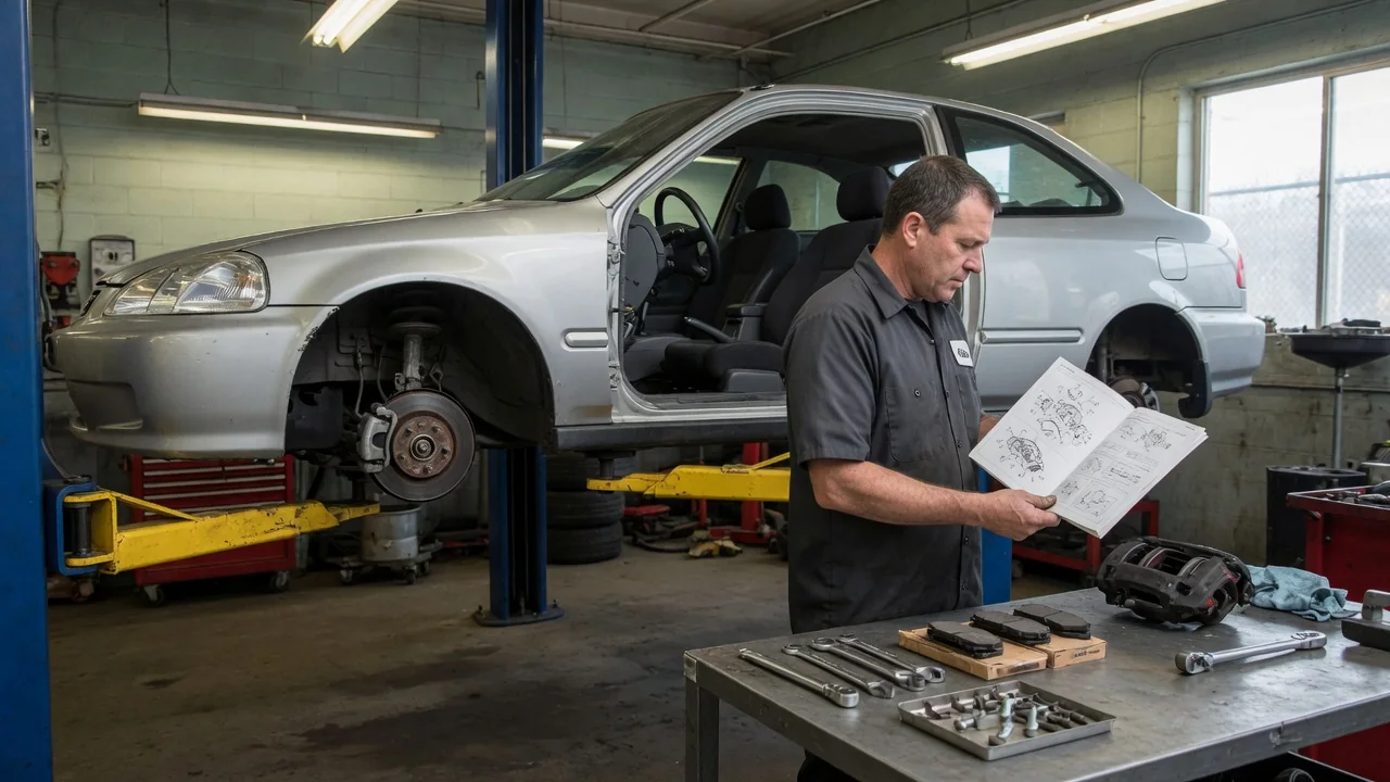
Anyone who has opened a service manual has seen parts floating apart along dotted lines and wondered why do car repair manuals show exploded diagrams instead of plain photographs. The answer is practical: an exploded view reveals how components stack together, which fastener belongs in which hole, and what order everything follows, all in a single drawing that a photo of an assembled part cannot match.
Part relationships
An assembled component hides most of what makes it work. Look at a front brake caliper on the vehicle and you see a casting, a hose, and the edge of the pads. An exploded diagram pulls that assembly apart along its axis, exposing the piston, the square-cut seal, the dust boot, the guide pins, and the anti-rattle hardware. Each part is drawn in its true orientation, so the reader can see which face meets which surface and which pieces nest inside others.
The dotted centerlines carry as much information as the parts themselves. They trace the path a bolt takes through a bracket, a spacer, and into a threaded boss, showing that three separate items share one fastener. On a door panel or a dashboard trim piece, those same lines reveal hidden clips and screws that sit behind covers. The exact count and placement of such hardware differs between makes, model years, and trim levels, which is why the drawing for the specific vehicle matters.
Assembly order
Because the parts are spread out along the direction they come off, an exploded view doubles as a sequence. The piece drawn farthest from the main body is generally the first removed and the last installed. A wheel hub illustration, for example, might show the dust cap, then the retaining nut, then a washer, then the outer bearing, each sitting further in. Reading from the outside toward the center gives the teardown order, and reading back out gives reassembly.
That sequence prevents the classic mistake of a leftover part on the bench. Thrust washers, shims, wave washers, and O-rings are thin, easy to overlook, and often directional. A drawing that shows a beveled washer facing a particular way, or a gasket sitting between two specific flanges, removes the guesswork that memory alone cannot. Some manuals pair the diagram with numbered steps, while others rely on the drawing alone, so the level of written guidance varies from one publisher and manufacturer to another.
Verification
Fastener identification is where these diagrams earn their place. A water pump or timing cover may be held by bolts that look alike in a pile but differ in length, thread, or shoulder design. The exploded view assigns each one a callout number tied to a legend, so a long bolt does not end up in a shallow blind hole where it could bottom out or crack a casting. Comparing the hardware in hand against the drawing is a quick, reliable check.
The same callouts help confirm that the right part is being ordered or refitted. Many manuals and parts catalogs link each numbered item to a description, and sometimes to notes about tightening values, single-use fasteners, or where sealant or thread locker applies. Those details are specific to each vehicle and should be read from the correct manual rather than assumed. After reassembly, counting the installed items against the diagram confirms that nothing was skipped and that every clip and seal went back.
Everyday Use and Observations
Exploded diagrams are useful well before a wrench comes out. Studying one in advance shows how deep a job goes, whether a component can be reached directly or sits behind several others, and which gaskets or seals are likely to need replacing once disturbed. An owner deciding whether to tackle a thermostat housing or a window regulator can judge the complexity from the number of layers drawn, then decide whether the task suits their tools and experience.
They also make conversations with a shop or parts counter easier. Pointing to a numbered item is clearer than describing a small bracket near the alternator. Readers will notice that drawing styles differ: factory service information tends to be detailed and model-specific, while general aftermarket manuals may cover several years or engines with one illustration. When the vehicle in the driveway does not quite match the picture, a mid-cycle design change or a different option package is usually the reason.
Limits and Next Steps
An exploded view shows arrangement, not condition or technique. It will not reveal that a bolt is seized, that a bearing is pressed in and needs special equipment, or that a part must be supported before another is released. The spacing between components is exaggerated for clarity, so the drawing is not to scale and says little about how tight the working room is. Wiring routes, hose paths, and fluid handling are often covered in separate illustrations.
For that reason the diagram works best alongside the written procedure, the specifications, and any safety cautions for the vehicle in question. Jobs involving airbags, fuel systems, high-voltage hybrid or electric components, or structural suspension parts carry risks a drawing cannot convey, and they are reasonable ones to leave to a qualified technician. A sensible next step is to confirm the manual matches the exact year, engine, and build of the car, then photograph each stage of disassembly as a personal supplement to the diagram.