What Is a Terminating Resistor on a CAN Bus?
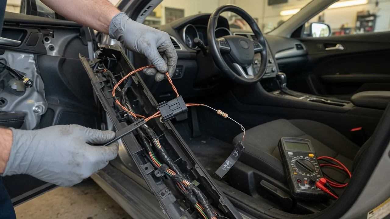
A terminating resistor on a CAN bus is a resistor, typically 120 ohms on a high-speed network, connected across the two data wires at each physical end of the bus. It is a small part with a big job: it keeps the electrical signal clean so every module on the network reads the same message. Understanding CAN bus termination in a car helps explain certain communication faults and why a simple resistance check is often one of the first diagnostic steps.
Signal quality: why the bus needs termination
Many modern vehicles use high-speed CAN, defined in ISO 11898-2, to let electronic control modules share data. The network uses a twisted pair of wires called CAN High and CAN Low, and information travels as a voltage difference between them. In the recessive state, which represents a logical 1, both wires sit near the same voltage, typically around 2.5 volts. In the dominant state, a logical 0, a transmitting module pulls CAN High toward roughly 3.5 volts and CAN Low toward roughly 1.5 volts. Receivers look at the difference, which makes the system resistant to electrical noise picked up equally on both wires.
At the speeds used on high-speed CAN, the wiring behaves as a transmission line. A twisted pair has a characteristic impedance, and the standard assumes about 120 ohms. When a signal edge reaches the end of a wire that is not matched to that impedance, part of the energy reflects back along the line. Those reflections can interfere with the following bits, causing ringing, distorted edges and voltage levels that receivers may misinterpret. A 120-ohm resistor at the end of the line absorbs the signal instead of bouncing it back, because the load matches the cable's impedance.
Termination has a second role that is easy to overlook. CAN transceivers actively drive the dominant state, but they do not actively drive the recessive state; they simply release the lines. The terminating resistors provide the path that pulls CAN High and CAN Low back toward each other. Without that load, the bus would return to the recessive level slowly, and at higher bit rates the transitions could blur together, upsetting the timing every module relies on to stay synchronized.
Network ends: where the resistors are located
High-speed CAN is designed as a linear bus: a main trunk with short branch connections, called stubs, to each module. Termination belongs at the two farthest ends of that trunk, one resistor at each end. Seen from the CAN High and CAN Low wires, the two 120-ohm resistors are in parallel, so the combined resistance across the network is about 60 ohms. Modules connected along the middle of the bus normally have no termination of their own, and their stubs are kept short so they do not create significant reflections.
Where those ends physically sit varies by manufacturer, model and network. In many vehicles the resistor is built into the circuit board of a module located at the end of the bus, such as an engine control unit, body control module, instrument cluster or gateway. Other designs place the resistor in a wiring harness, connector or junction block. Some modules exist in terminated and non-terminated versions that look alike from the outside. The location of termination on a particular vehicle should therefore come from its wiring diagrams or service information rather than assumptions.
Not every network uses the same scheme. Some designs use split termination, where each end has two 60-ohm resistors in series with a capacitor from their midpoint to ground; this still presents about 120 ohms per end between the data wires while helping filter common-mode noise. Fault-tolerant low-speed CAN, defined in ISO 11898-3, distributes termination across the nodes instead of concentrating it at two ends. Many vehicles also run several separate CAN networks joined by a gateway module, and each high-speed network has its own pair of ends.
Testing CAN bus termination
The most common first check is a resistance measurement between CAN High and CAN Low with the network powered down. A typical approach is to switch the ignition off, allow the modules to go to sleep and disconnect the battery so the meter is not reading through active electronics. On many vehicles the diagnostic link connector provides access, with CAN High on pin 6 and CAN Low on pin 14 under the standard OBD-II pin assignment. However, that connector may reach only one of several networks, sometimes behind a gateway, so back-probing a module connector or a splice point shown in the wiring diagram may be necessary.
Interpreting the result follows directly from the parallel arrangement. A value near 60 ohms suggests both terminating resistors are present and connected. A value near 120 ohms suggests one end is missing: an open resistor, a disconnected module that contains the termination, or a break in the wiring between the measurement point and one end. A reading well below 60 ohms can indicate an extra terminator or a partial short between the wires, while a reading near zero points to CAN High and CAN Low shorted together. An open circuit suggests the measurement point is isolated from both ends. Disconnecting modules one at a time while watching the reading helps locate the problem.
A resistance check confirms the static load but says nothing about how signals behave while the network is running. For that, technicians use an oscilloscope with two channels or a differential probe to view CAN High and CAN Low with the vehicle awake. A healthy waveform shows clean, square transitions with mirror-image traces on the two lines. Missing or incorrect termination often appears as ringing on the edges, a slow return to the recessive level or distorted voltage levels.
Practical implications and limits
For a car owner, termination matters mostly when communication faults appear. Network problems can produce communication-related trouble codes, often in the U-code range, along with warning lights, gauges that drop out or modules that do not respond to a scan tool. Termination is only one possible cause, alongside corroded connectors, chafed wiring, water intrusion, a failing module or low system voltage. A network with a missing terminator may still work some of the time, which is why such faults can come and go with temperature, vibration or electrical load.
Termination also explains why adding or replacing hardware on the bus deserves care. An aftermarket device that taps into CAN and includes its own terminating resistor adds a third load, lowering total resistance to roughly 40 ohms and reducing signal levels. Installing a used or replacement module of the wrong variant can remove a terminator or add an extra one. Matching part numbers and following the manufacturer's repair procedure helps avoid problems that are difficult to trace later.
A correct 60-ohm reading is a useful starting point, not a clean bill of health. It does not reveal intermittent breaks that only open under movement, a module whose transceiver is failing or noise coupled in from other systems. Meter accuracy, test lead contact and circuits left connected can also shift readings slightly. Expected values, access points and network layouts are vehicle-specific, so service information for the exact vehicle remains the authority when diagnosing CAN bus termination problems.