Tools Needed for Timing Belt Replacement
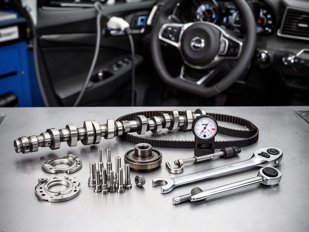
Timing belt replacement tools are engine-specific equipment used to locate shafts, hold pulleys, measure belt tension, adjust the tensioner, and remove certain pulleys. A general timing belt tool or kit cannot establish that it matches the factory service procedure. The engine code and vehicle details determine which tools for timing belt work apply. This overview explains what each category is for so the correct equipment can be identified before the job is scheduled.
Identify the Tool Requirements for the Exact Engine
The list of timing belt replacement tools depends on the engine and the specified factory service procedure, not on a generic kit label. A timing belt tools assortment sold for many applications cannot establish suitability for a particular vehicle. Service information identifies fixtures, pins, plates, gauges, and adapters by tool reference, and those references change with engine family and revision. Matching the engine code, model year, and related vehicle details to that documentation is how the required timing belt tool set is identified before any parts are ordered or the job is planned.
Once the engine is identified, the equipment groups by purpose rather than by kit packaging. Locating fixtures hold camshafts and the crankshaft at specified positions, while holding tools resist fastener torque on pulleys. Measuring instruments check belt tension, and adjustment wrenches or sockets interface with the tensioner. Pullers remove specified pulleys only when the procedure requires that method. This grouping supports planning which timing belt tools the job will actually use. It does not replace or describe a timing belt replacement procedure, and it cannot authorize a job without the matching service information.
Camshaft and Crankshaft Locks Establish Specified Positions
A camshaft locking plate, crankshaft locating pin, and other engine-specific locating fixtures are intended to place shafts at the positions called out in the service procedure. Some engines use plates that engage cam slots or sprocket features. Others use pins that pass through a designated hole in a pulley or crank flange. The geometry of a fixture is not proof of fit. A plate or pin that looks similar to another engine's timing belt tool hardware can still miss the intended engagement, sit at the wrong depth, or belong to a different timing arrangement entirely.
Locating pins and locking fixtures must not be assumed suitable for resisting fastener torque. The procedure may require a separate pulley holding tool when a bolt is loosened or tightened, because a thin plate or locating pin can bend, shear, or allow the shaft to move. Incorrect shaft positioning can cause valve and piston contact or leave the belt installed out of time. When the correct locating equipment or factory service procedure is unavailable, the work needs professional attention rather than substitution with an unconfirmed fixture.
Tension Gauges Check the Specified Belt Tension
A belt tension gauge, whether mechanical or sonic, is a timing belt tension tool used to check the specified setting rather than a universal target. Mechanical instruments convert belt deflection or strand force into a reading. Sonic instruments convert a vibration frequency into an equivalent tension value after the correct span, belt mass, and instrument settings are applied. Those readings are valid only at the prescribed measurement location and under the conditions the procedure states. Changing span length, temperature, or which strand is measured can change the result even when the belt has not been adjusted.
The engine procedure, not the presence of a gauge in a kit, decides whether tension is verified with an instrument, a tensioner indicator window, an automatic tensioner stop, or another specified method. Some designs never call for a handheld gauge. Belt feel, deflection by hand, and operating noise cannot establish correct tension, because those cues vary with belt construction, temperature, and accessory load. If the prescribed method cannot be followed, or if a reading is uncertain because of instrument settings or access, qualified verification is required before the engine is returned to service.
Tensioner Tools Provide the Required Adjustment Interface
A timing belt tensioner tool is the interface that actually moves or holds the tensioner during adjustment, and its form follows the tensioner design. Pin spanners engage holes in a pulley face or eccentric. Offset wrenches and a tensioner adjustment wrench reach recessed hex features. Specified sockets or Torx drives fit the adjuster fastener when that is the prescribed contact. Fit must match the documented interface. An undersize pin, the wrong offset, or a socket that only partially seats can round the feature or load the tensioner housing instead of the intended adjuster.
Adjustment and verification are separate actions. The tensioner tool moves the tensioner while a gauge or the prescribed indicator checks the resulting setting. Some designs also require dedicated retaining pins or compression equipment to hold a hydraulic or spring tensioner in a service position, but only when the exact service procedure calls for that hardware. An ill-fitting tool or an improvised lever can crack the tensioner body, damage the bearing, or leave the belt overloaded or underloaded. Tensioner loading and release sequences belong in qualified repair guidance, not in improvised shop practice.
Pullers, Holding Tools, and Access Equipment Serve Separate Tasks
A pulley puller is needed only where the specified removal method requires one. Many timing belt jobs never call for a puller, while others require a dedicated hub puller, a harmonic balancer puller, or a specified adapter set to draw a crank or cam pulley off a tapered or keyed fit. Confirming the correct attachment points and adapters against service information is part of tool selection. Using the wrong holes, jaw style, or forcing against a thin pulley web can distort the component. This confirmation is not a removal procedure and does not describe pulley extraction.
A dedicated pulley holding tool keeps a sprocket or crank pulley from turning while a fastener is loosened or tightened, and its required capacity must come from service information rather than from an estimate of bolt size. Locating fixtures are not substitutes for that holding function. A torque wrench and suitable sockets are additional requirements when the procedure specifies fastener torque. Approved engine support equipment may also be needed when access work requires the engine or subframe to be supported. Support and lifting methods belong in the vehicle's service information; they are not described here.
Check Kit Contents and Readiness Before Scheduling the Job
Before the job is scheduled, every required fixture and adapter should be checked against documented engine coverage and the service tool references for that engine code. A timing tool kit often includes only locking plates and pins. It may omit the belt tension gauge, timing belt tensioner tool, pulley puller, pulley holding tool, torque wrench, or access equipment the procedure actually uses. Coverage charts that list an engine family can still miss a revision that changed the tensioner interface or locating pin. Confirming each referenced item individually is how suitability is established.
Readiness also includes physical condition. Bent locking plates, worn pin diameters, rounded hexes, and cracked puller jaws can prevent correct location or damage components. Measuring equipment must meet its calibration requirements, because an out-of-date sonic or mechanical gauge can report a plausible reading that does not match the specified tension. Missing service information, uncertain tool fit, inadequate support equipment, or an inability to verify timing or tension are reasons to arrange professional service instead of proceeding. Those gaps are planning stops, not invitations to substitute unconfirmed hardware.