How to Test an Oxygen Sensor With a Multimeter and Read Its Voltage
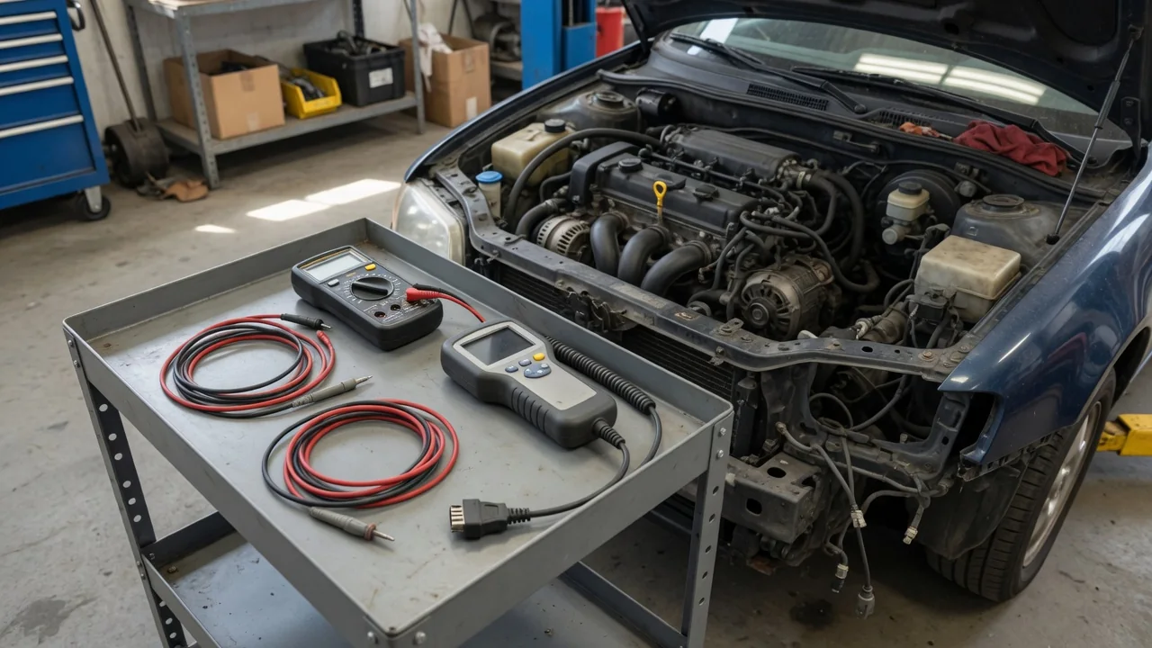
Oxygen sensor testing starts with identifying the sensor, meeting required conditions, and choosing the right instrument. How to test an oxygen sensor with a multimeter, a scan tool, or a dedicated oxygen sensor tester all aim at reading signal voltage and interpreting switching in context. Normal oxygen sensor readings depend on design, temperature, and closed-loop operation. A stuck high or low voltage is evidence to interpret, not proof the part has failed.
Identify the Sensor and Its Required Test Conditions
Before any oxygen sensor test, confirm the vehicle, engine, bank, and sensor number so you are not measuring the wrong circuit. Upstream and downstream sensors, and Bank 1 versus Bank 2 on a V-type engine, do not share the same expected behavior. Vehicle service information identifies sensor technology, connector terminals, the signal reference, and the expected output. That documentation also tells you whether you are dealing with a narrowband oxygen sensor or a wideband air-fuel sensor, which changes the entire diagnostic path.
The familiar oxygen sensor voltage test with a meter applies only to designs that output a conventional switching signal. A wideband air-fuel sensor, sometimes called a lambda sensor in live data, needs its specified procedure, not a generic 0-to-1-volt check. Testing oxygen sensor output is also inconclusive until the heater has brought the element to operating temperature and the controller has entered closed-loop operation. A cold sensor or open-loop fuel control can hold the reading away from its normal working range even when the part itself is capable of responding.
Select Test Equipment and Set Up Safely
Oxygen sensor testing on a running vehicle usually means a high-impedance multimeter, a compatible scan tool, or, when the design supports it, a dedicated oxygen sensor tester. A high-input-impedance digital meter is used so the instrument does not load a small signal voltage. On a scan tool, select the live data parameter that matches the sensor you identified, then check units, sensor identity, and manufacturer-defined scaling. Oxygen sensor readings on a graph or PID list are only useful if that parameter actually belongs to the circuit under test.
Any running-engine observation needs outdoor ventilation. Keep people, cables, and equipment clear of hot exhaust, belts, and cooling fans. When you test an oxygen sensor with a multimeter, make connections with the engine off, using the documented terminals and sensor ground. Do not pierce insulation, guess at pins, or reach a sensor under a vehicle that is not properly supported. If terminal access is uncertain, stop and have a technician complete the oxygen sensor test rather than improvising a backprobe.
Measure an Approved Oxygen Sensor Signal With a Multimeter
For a compatible voltage-output sensor, how to test an oxygen sensor with a multimeter begins by selecting DC voltage and using the manufacturer-approved test connection and signal reference. The oxygen sensor test multimeter setup typically measures between the signal wire and the specified ground, not an assumed chassis point. A connected-circuit measurement may be required. Unplugging the sensor can change circuit behavior or leave you reading a controller bias voltage instead of true oxygen sensor voltage. That bias is a module output, not a live exhaust reading.
Observe oxygen sensor voltage movement only after the specified temperature and closed-loop conditions are met. A digital meter can average or miss rapid signal switching, so a relatively still display does not by itself prove the sensor is stuck. Never apply external voltage, never use current mode across signal terminals, and never measure resistance on a powered circuit. Testing an oxygen sensor with a multimeter is a voltage observation, not a powered ohms check. If pin identification is uncertain, do not test an oxygen sensor with a multimeter by guessing; send that access work to a technician.
Read Voltage Range and Switching in Context
A conventional heated zirconia narrowband oxygen sensor commonly operates around 0.1-0.9 volts when hot, and that oxygen sensor voltage range is a typical working window, not a substitute for vehicle-specific specifications. Low voltage indicates oxygen-rich exhaust; high voltage indicates oxygen-poor exhaust. During suitable closed-loop operation, an upstream narrowband sensor should show signal switching as mixture control moves across stoichiometric. Do not assign a universal switching frequency or pass threshold. Normal oxygen sensor readings for that sensor are the values and movement the service information defines under the stated test conditions.
Downstream oxygen sensor voltage often looks steadier because catalyst operation and test conditions shape the trace. A relatively steady downstream reading alone does not establish sensor failure. Wideband scan data may report lambda, equivalence ratio, pump current, or a scaled voltage; interpret the selected parameter using its documented definition rather than treating it as a narrowband 0-to-1-volt signal. Scan-tool graphing and update rate also change what you see. When response time or true signal switching must be judged, professional oscilloscope testing is the appropriate next step.
Interpret a Reading That Stays Low
A low voltage oxygen sensor result is meaningful only after the technology and circuit specification are confirmed. On a conventional zirconia narrowband sensor, persistent oxygen sensor voltage low can reflect excess exhaust oxygen, an exhaust leak upstream of the sensor, a signal-circuit problem including a poor sensor ground, or a sensor fault. Oxygen sensor low voltage is therefore a circuit-and-exhaust observation, not a one-step part diagnosis. Confirm you are still watching the correct live data or meter channel before treating the reading as stuck.
Record operating temperature, control mode, fuel trims, and any related diagnostic information while the condition exists. Do not create a lean mixture just to force the display. A single low reading cannot identify the failed part, because mixture, leaks, wiring, and the sensor can all produce similar oxygen sensor readings. When controlled response testing, exhaust inspection, or circuit testing is needed, a technician should perform those checks. How to test the oxygen sensor in that situation is no longer a simple meter snapshot; it is a comparison of command, exhaust condition, and circuit integrity.
Interpret a Reading That Stays High
A high voltage oxygen sensor result must be judged against the documented range and the test conditions in effect, including any controller bias or scan-data scaling. On a conventional zirconia narrowband sensor, sustained oxygen sensor voltage high can reflect oxygen-poor exhaust, a signal-circuit fault such as a short toward the high reference, or a sensor problem. Oxygen sensor high voltage on a wideband or scaled PID may simply mean a different unit, so do not treat every elevated number as a rich exhaust indication. Match the parameter definition before interpreting the magnitude.
Note whether the high reading persists under the prescribed hot, closed-loop conditions, and review available fuel-trim and fault-code context without inducing a rich mixture. A diagnostic code is evidence to interpret, not proof a part has failed, and manufacturer-dependent codes require vehicle-specific confirmation of meaning before you act on them. If the oxygen sensor voltage stays high while related data do not support a consistently oxygen-poor exhaust, professional circuit and response testing is needed before condemning the sensor. Further testing then belongs in a shop with the correct pinout and capture tools.